

Ideal three windings transformer#
Block appearance in REPEAT VISION#
The Ideal three windings transformer block is a model of a perfect three-winding transformer described by the following expressions (1):
where:
\(K_1\) - transformation ratio between primary and secondary windings;
\(K_2\) - transformation ratio between primary and tertiary windings;
\(U_1\), \(U_2\), \(U_3\) - voltages of primary, secondary and tertiary windings, [V];
\(I_1\), \(I_2\), \(I_3\) - currents of primary, secondary and tertiary windings, [A].
The equivalent circuit (with load in the form of resistances R) is shown in Fig. 1:
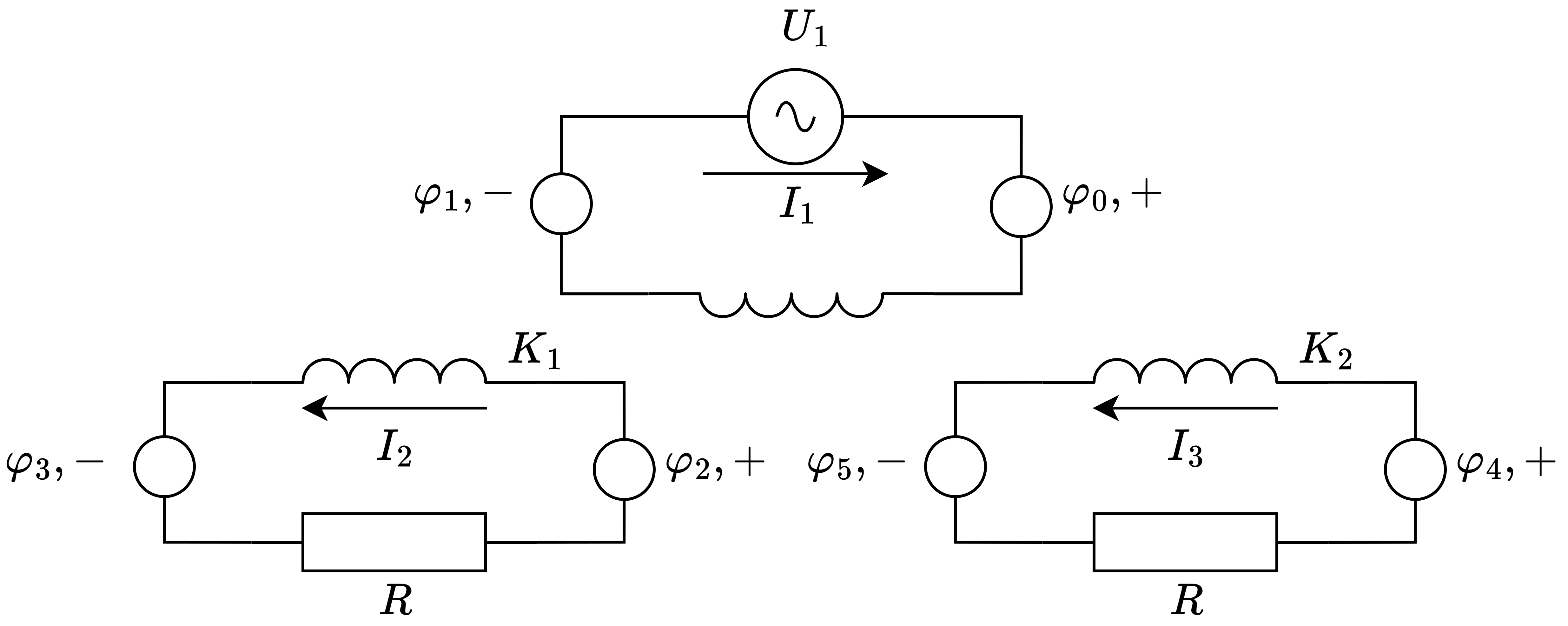
Fig. 1 Equivalent circuit#
1. Properties#
Property |
Default value |
Description |
Units of measurement |
|---|---|---|---|
Winding ratio of primary and secondary windings |
0.001 |
- |
- |
Winding ratio of primary and tertiary windings |
0.001 |
- |
- |
2. Inputs and outputs#
Parameters |
Input/Output |
Description |
Units of measurement |
Port type |
|---|---|---|---|---|
Primary winding + |
Input |
- |
- |
Electronics |
Secondary winding - |
Input |
- |
- |
Electronics |
Tertiary winding - |
Input |
- |
- |
Electronics |
Primary winding - |
Output |
- |
- |
Electronics |
Secondary winding + |
Output |
- |
- |
Electronics |
Tertiary winding + |
Output |
- |
- |
Electronics |
In order to see the connection capabilities of the block, you need to go to page Description of block ports
See also
An example of using this block can be found in subsection Power industry of section Electrical equipment practical guide Modeling of zero-sequence current directional protection of 220 kV power transmission lines.