

Embedded projects#
The application allows to create circuits from blocks, which are essentially independent subprojects. For this purpose, the Project block functionality is used from the External models library section (see Fig. 1 below). This figure shows the Project_1 embedding into Project_2 in the form of block №2.
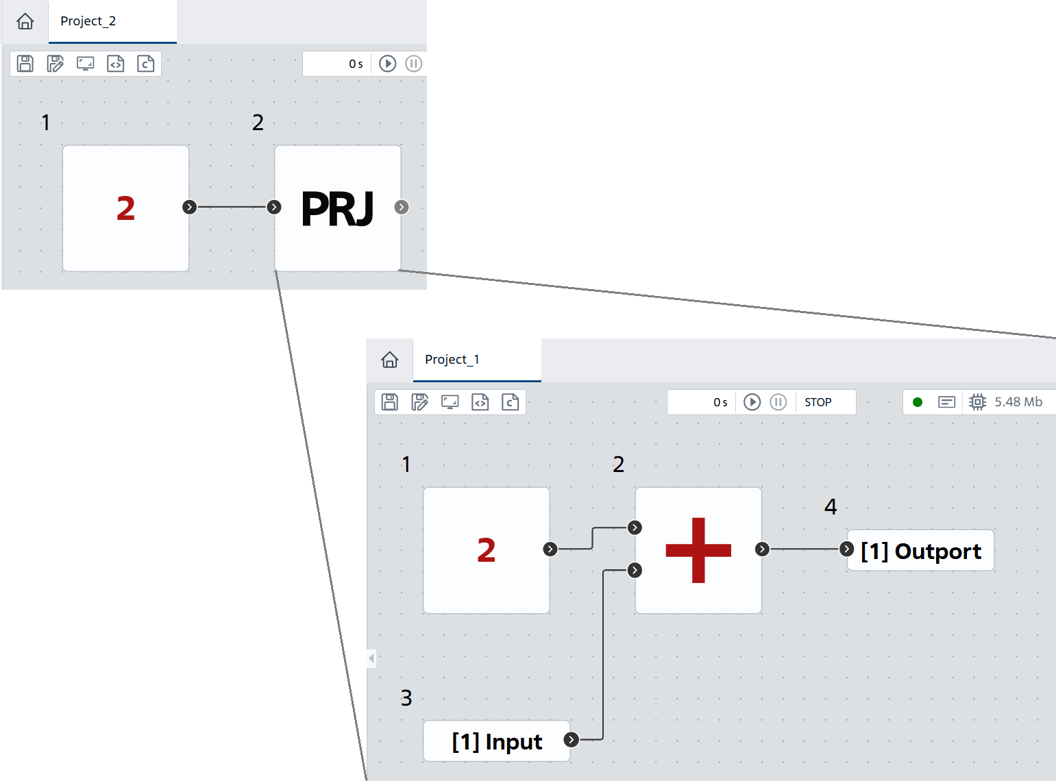
Fig. 1 Illustration of Project_1 embedding in Project_2 (block №2)#
The figure above shows a minimal two-level embedding circuit, but functionally there were no restrictions imposed on number of such levels. The limitation is the ability to “fail” several levels down at once to view or edit if the number of such embedding levels is designed to be three or more. For this purpose, it is necessary to sequentially «move» down or up from level to level with step 1.
1. Create a subproject#
It is necessary to create subprojects in advance for practical realization of Project block use, which will be components of embedding according to the «bottom-up» principle. Thus, for the example (see Fig. 1 above), first a model circuit named Project_1 was created and saved as a subproject, then a model circuit named Project_2 was created . The application will request to select a previously created project (in this case Project_1) as a subproject from the drop-down menu when adding this block, Fig. 2:
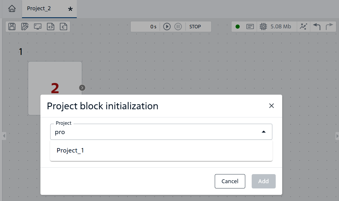
Fig. 2 Selection Project_1 subproject#
Thus, a block appears in the circuit of Project_2 model, «falling» inside of which, in the right panel appears the possibility to view or edit Project_1 properties, Fig. 3:
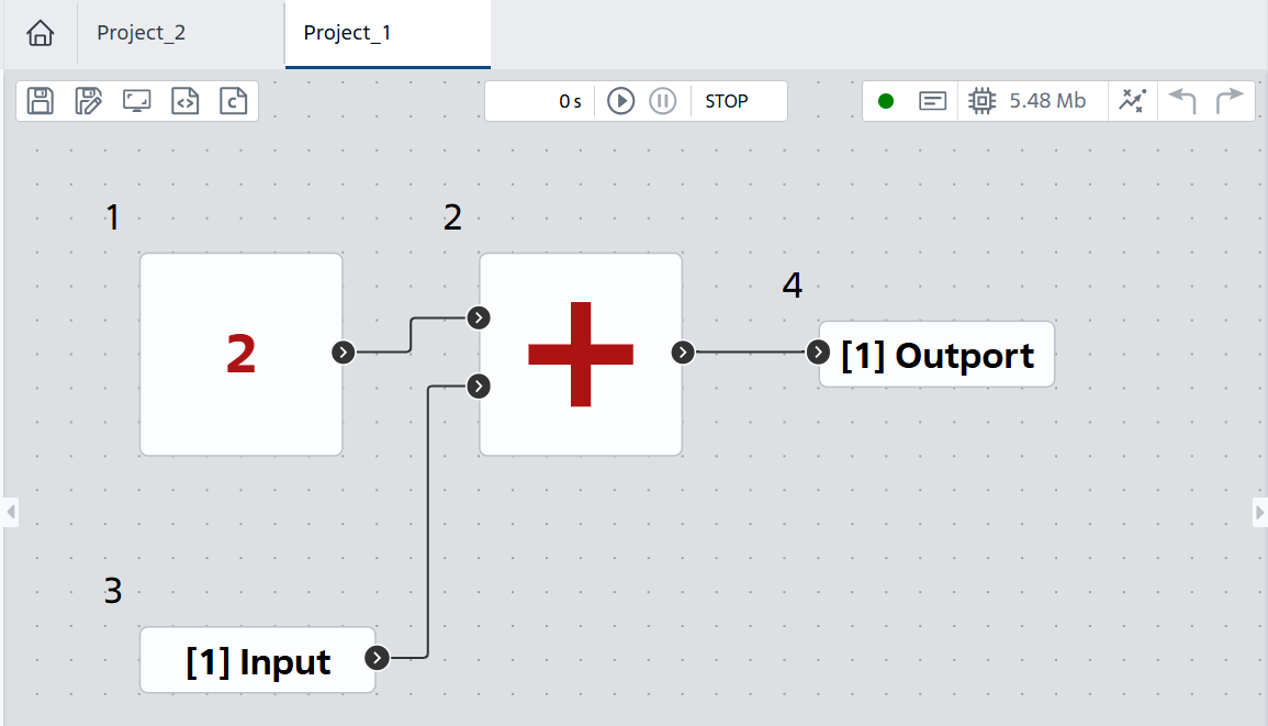
Fig. 3 View Mode illustration for Project_1 from Project_2#
2. Definition of «external» subproject blocks#
At this step it is necessary to define which blocks from subproject Project_1 will be «external», i.e. whose properties can be changed at Project_2 level. Let this «external» block be block №1 Constant (see Fig. 4 below). When selecting the name Constant 1 from the drop-down menu in the right-hand panel of the Application under the Block tab.
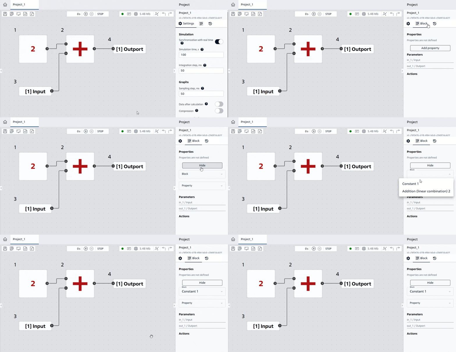
Fig. 4 Selecting «external» properties#
3. a id=”title8”>”Purpose of the property and values for the «external» block#
The next step is to define the properties and value. Select the Constant value property and set its value to 25, Fig. 5:
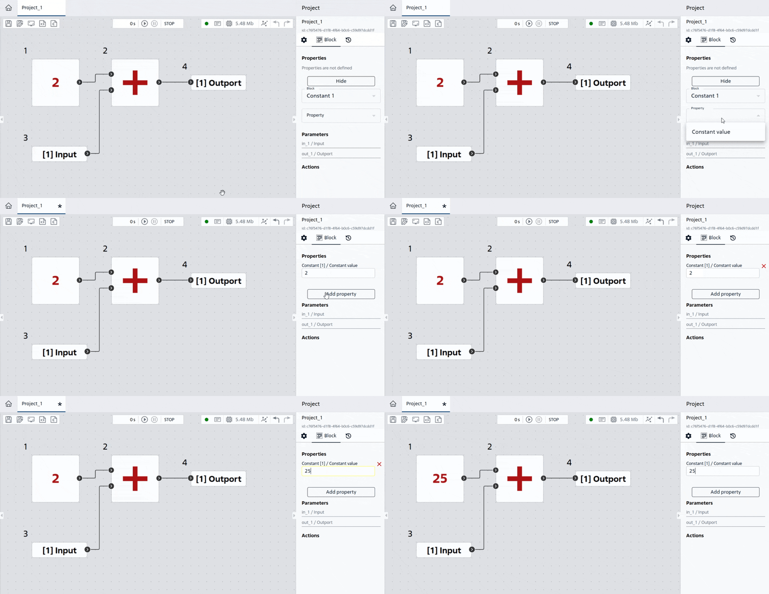
Fig. 5 Definition of a property and its value#
When you open Project_2, a message will appear, Fig. 6:
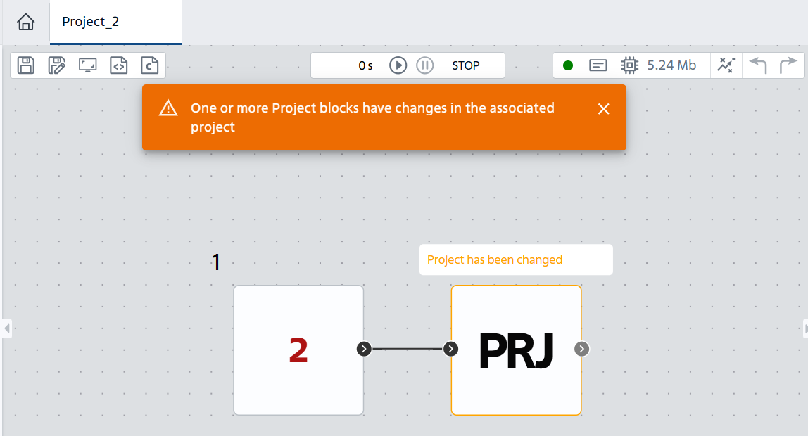
Fig. 6 Message about changes#
Assigning a property value to the Project block is performed similarly to steps 2 and 3 (see Fig. 7 below). As a result, the constant value 25 was assigned to the Project block at the Project_2 level (see Fig. 8 below).
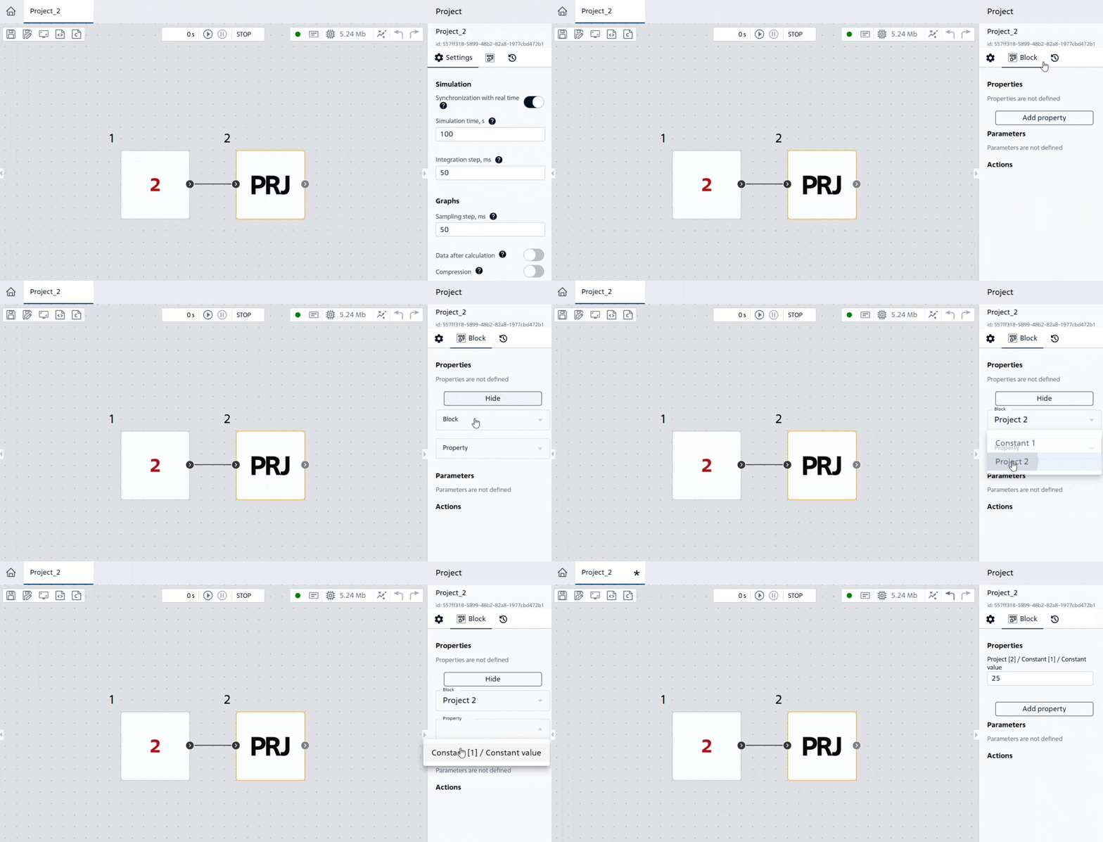
Fig. 7 Assigning a property value to the Project block#
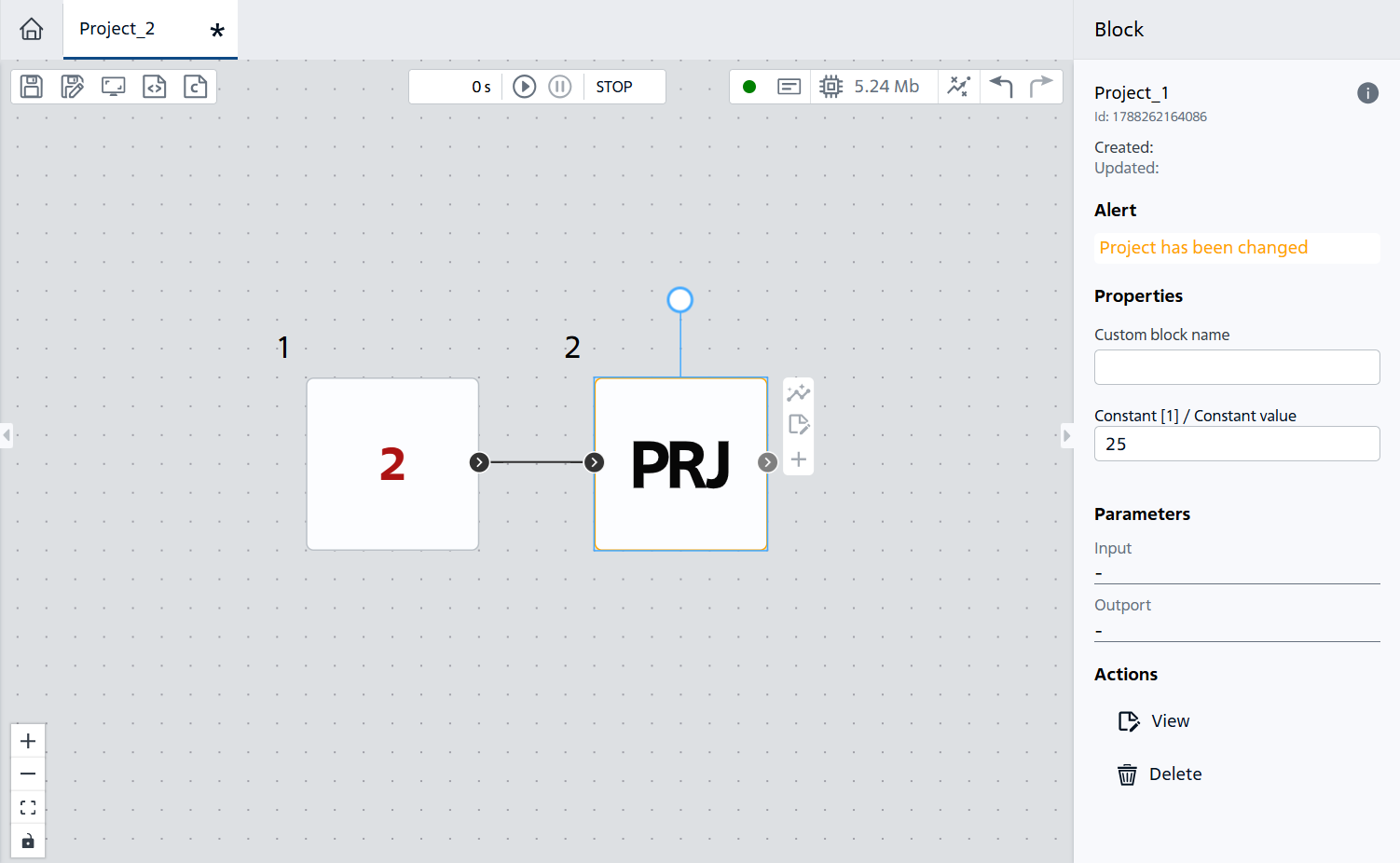
Fig. 8 Result of assigning a property to the Project block#
4. Rename properties#
For ease of visual use of the properties of the Project block, it is possible to edit the names of these properties. To do this you need (see Fig. 9 below):
Go to the
Blocktab;Double-click LMB on the property name to invoke editing mode;
Accept the changes by clicking the button
 to the right of the new property name.
Fig. 9 Renaming properties#
To edit custom names for the Inport and Outport port blocks, you need to (see Fig. 10 below):
Select the port block by clicking on it with LMB;
Change the name in the
Custom block nameproperty column.
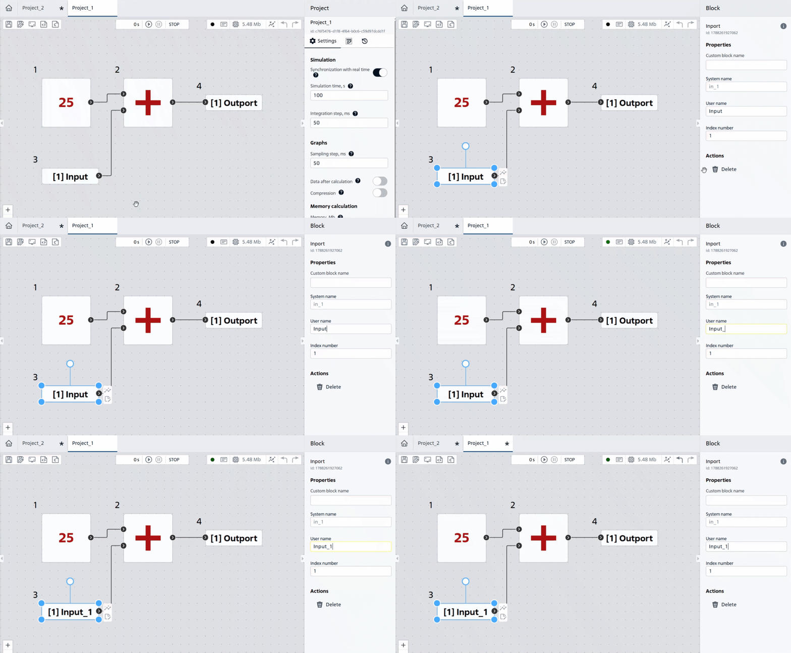
Fig. 10 Editing the custom name of the Inport block#
5. Checking the circuit operation#
level, it is necessary to run the calculation by clicking the icon  . But first, let’s analyze the logic of the Addition (linear combination) block’s. The Addition (linear combination) block will sum from the two sources:
Constant value of block №1 at
Project_1level (equal to 25 (see Fig. 10 above));The values at the port of the block Inport, which is the output of the constant of block №1 at the level of
Project_2(equal to 2, see Fig. 11 below).
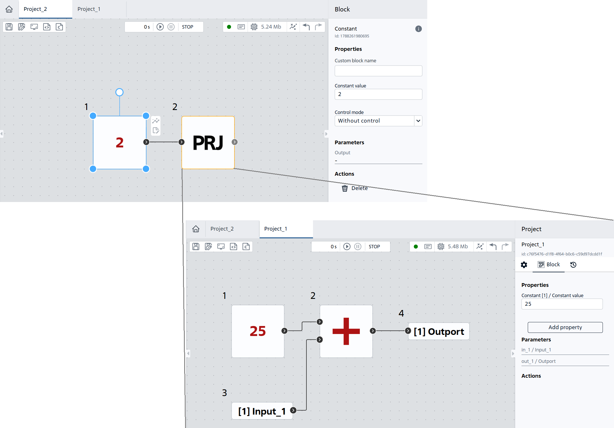
Fig. 11 The value of the constant of block №1 at the Project_2 level#
Thus, after starting the calculation, the result at the block output will be equal to 27, Fig. 12:
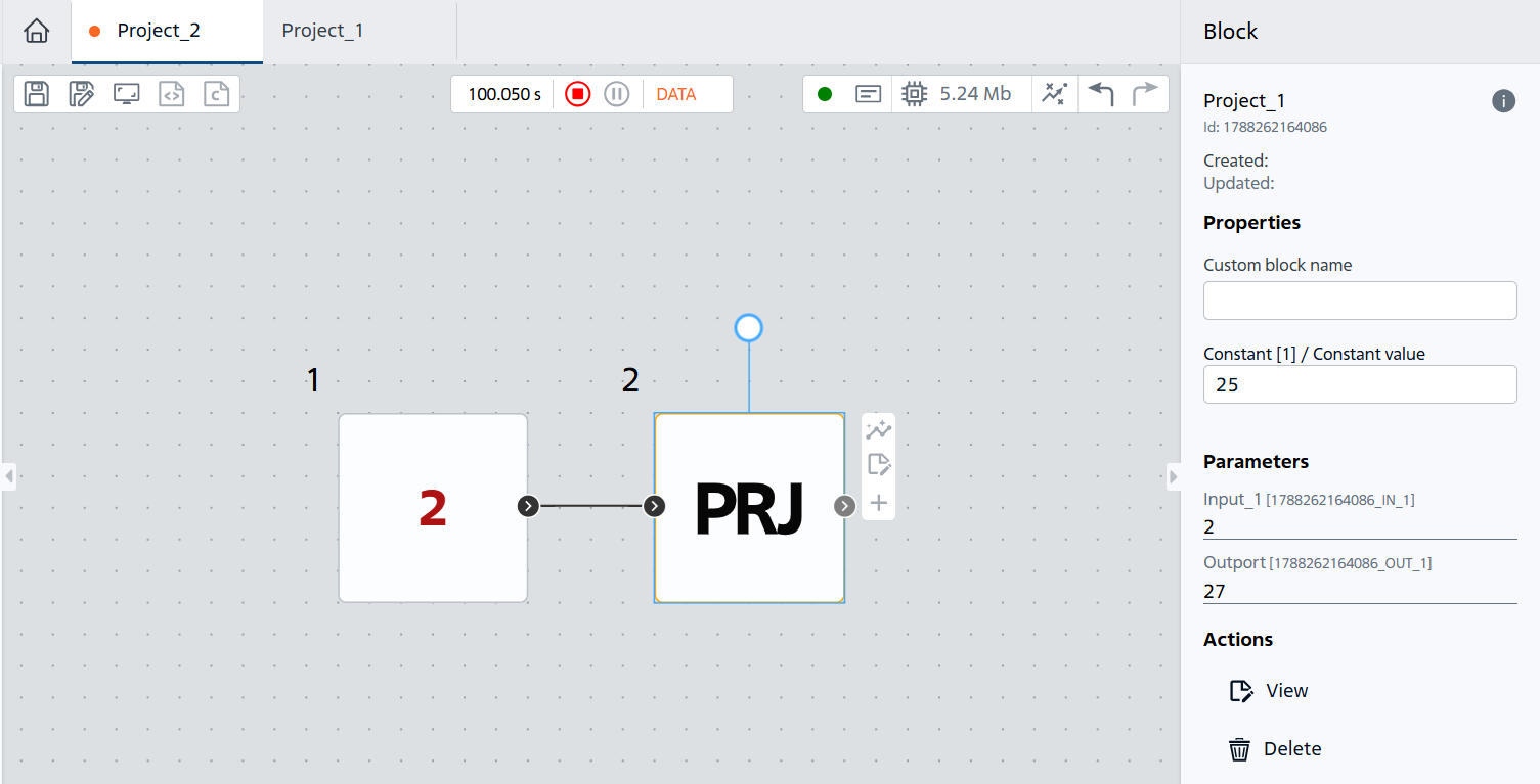
Fig. 12 Result of running the calculation at the Project_2 level#