

SA AEC#
Block appearance in REPEAT VISION#
Automatic excitation control (AEC) is a device that acts on the excitation system of synchronous machines to maintain the voltage in the electrical network at a given level.
This unified regulator was installed on all types of synchronous machines as part of various excitation systems (independent, self-excitation systems and brushless) until 1983. A fairly detailed mathematical description of the SA AEC regulator was developed. However, the parameters of the SA AEC magnetic amplifiers have a wide range, so during the process of adjusting the regulator, changes had to be made to its circuit for each generator in accordance with specially developed recommendations. Below are the mathematical model (1) and the corresponding simplified structural diagram of the SA AEC (see Fig. 1 below), which allows for any noted changes in the characteristics of natural regulators to be taken into account by varying the parameters.[1]
where:
\(I_{RГ}\) - reactive current of the generator;
\(X_{comp}\) - share of compensation of the transformer reactive resistance;
\(I_f\) - rotor current;
\(f_U\) - generator voltage frequency;
\(K_{0U}, K_{1U}, K_f, K_{1f}, K_{1If}\) - gain factors in voltage regulation and stabilization channels;
\(T_1\) - \(T_6\) - time constants of the channels and the output adder.
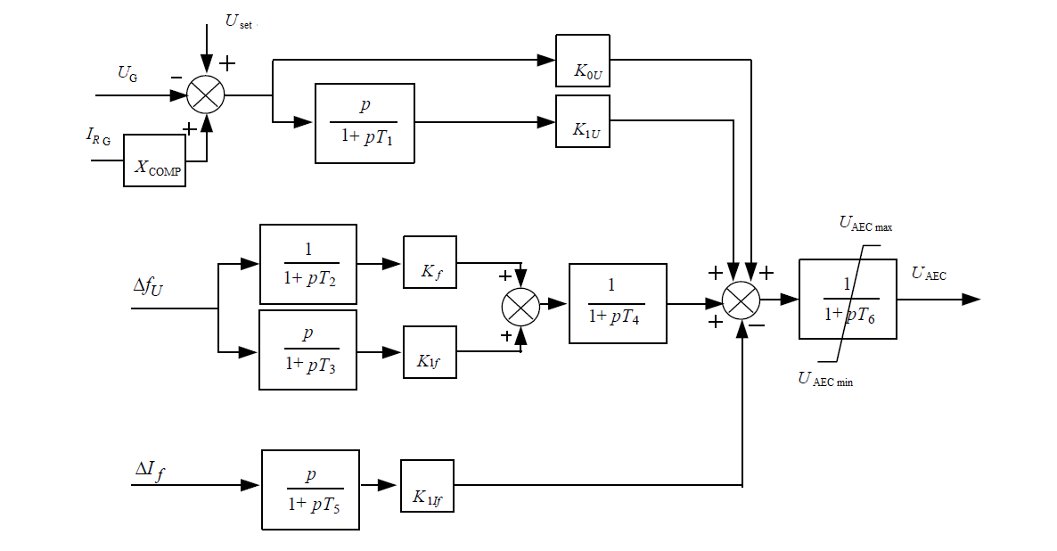
Fig. 1 Structural diagram of the SA AEC#
1. Properties#
Properties |
Default Value |
Description |
Units of measurement |
|---|---|---|---|
Voltage gain factor |
50 |
– |
– |
Voltage derivative gain |
5 |
– |
– |
Frequency gain |
2 |
– |
– |
Frequency derivative gain |
5 |
– |
– |
Rotor current derivative gain |
5 |
– |
– |
Transformer resistance |
0.2 |
– |
r.u. |
Statism |
8 |
– |
% |
Time constant of the differentiating element of the voltage regulator channel |
0.06 |
– |
s |
Time constant of the 1st inertial link of the system stabilizer channel |
0.09 |
– |
s |
Time constant of the 2nd inertial link of the system stabilizer channel |
0.09 |
– |
s |
Time constant of the differentiating link of the internal motion stabilizer channel |
0.15 |
– |
s |
Time constant of the inertial link of the output adder |
0.04 |
– |
s |
Maximum value of AEC voltage |
6 |
– |
V |
Minimum value of AEC voltage |
-6 |
– |
V |
2. Inputs and outputs#
Parameters |
Input/Output |
Description |
Units of measurement |
Port type |
|---|---|---|---|---|
Voltage setting |
Input |
– |
V |
Automation |
Generator voltage |
Input |
– |
V |
Automation |
Generator stator reactive current |
Input |
– |
A |
Automation |
Generator voltage frequency deviation |
Input |
– |
Hz |
Automation |
Rotor current deviation |
Input |
– |
A |
Automation |
Voltage AEC |
Output |
– |
V |
Automation |
In order to see the connection capabilities of the block, you need to go to page Description of block ports