

Full-bridge converter#
Block appearance in REPEAT VISION#
The block implements a model of a single-phase converter built according to a bridge diagram. The switching device of the converter is a special component, IGBT transistor, connected in parallel with the reverse diode. The bias voltage of the transistor and diode are not considered. RC damper circuit can be connected in parallel to each pair of these components.
Switching devices of the converter are controlled by an input vector signal of the form [S1, S2, S3, S4] coming to the Control port. Indices of vector signal components correspond to numbering of switching devices in the diagram (see Fig. 1 below). Control can be carried out using Two level PWM generator when 2 arm is selected in Bridge converter type property, as well as using individual pulses generated by the Automation section blocks and collected into one vector signal with dimension equal to 4 using the Multiplexer block.
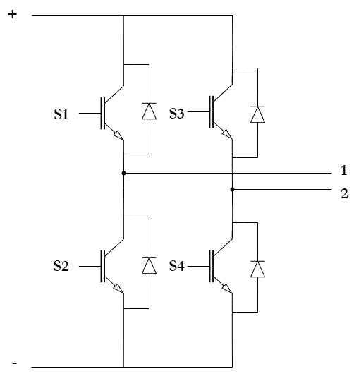
Fig. 1 Single-phase bridge converter diagram#
1. Properties#
Property |
Default value |
Description |
Units of measurement |
|---|---|---|---|
On-state resistance |
0.001 |
- |
Ohm |
Off-state resistance |
1.0e8 |
- |
Ohm |
On |
- |
- |
|
Snubber resistance |
1000000.0 |
Available, when |
Ohm |
Snubber capacitance |
1000000.0 |
Available, when |
F |
2. Inputs and outputs#
Parameters |
Input/Output |
Description |
Units of measurement |
Port type |
|---|---|---|---|---|
Control |
Input |
- |
- |
Automation |
+ |
Input |
- |
- |
Electronics |
- |
Output |
- |
- |
Electronics |
1 |
Output |
- |
- |
Electronics |
2 |
Output |
- |
- |
Electronics |
In order to see the connection capabilities of the block, you need to go to page Description of block ports
3. Examples of use#
Examples of using this block can be found in the following sections:
Tutorials
Library |
Tutorial name |
|---|---|
Electronics |