

Single machine power system powered by inverter#
This tutorial describes simple steps to simulate an inverter in a single machine power system.
In this tutorial, you learn how to simulate an inverter in a single-phase power system. This power region comprises a DC voltage source, a single-phase bridge converter (inverter), an inverter control system and a load. As a result of the calculation, it is necessary to determine the actual voltage value of the single-phase network.
1. Project creation and setup#
First you need to create a new project and give it a name, for example, Single machine power system powered by inverter.
In the next step, one needs to make the following settings (see Fig. 1 below):
Setup |
Value |
|---|---|
Off |
|
2 Simulation time |
0.3 [s] |
3 Integration step |
0.05 [ms] |
4 Sampling step |
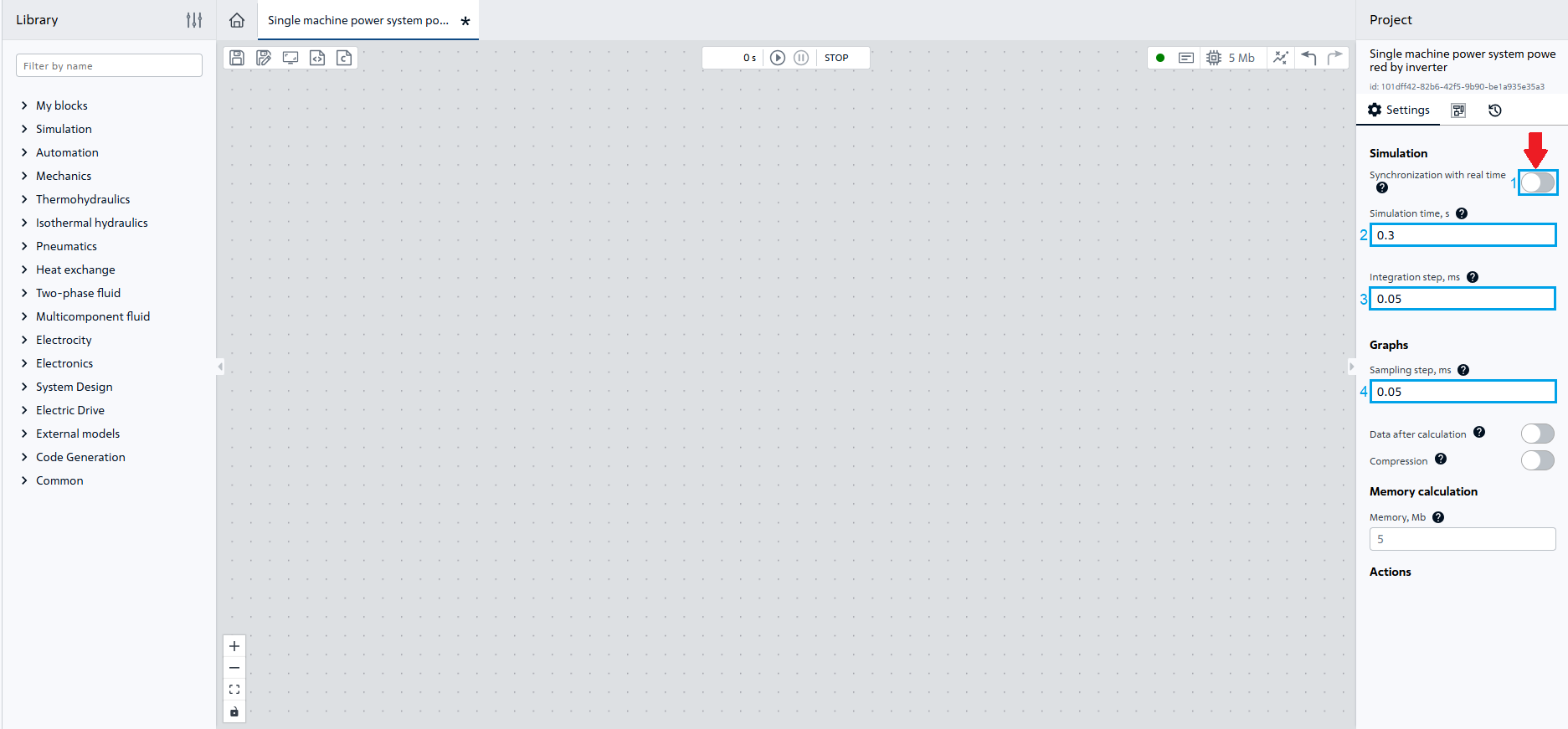
Fig. 1 Project setup#
Note
Disable parameter to set the simulation time to < 1[s]
Important
In REPEAT VISION decimal numbers are specified through a period.
Let’s start the basic steps for creating a diagram by opening the library Electronics.
2. Creating a DC voltage source#
Add block №1 of our diagram, for this purpose we will transfer it to the workspace of block Voltage source for power supply of this power region.
In the properties of block №1 specify (see Fig. 2 below):
Value |
|
|---|---|
1 Voltage |
400 [V] |
2 Internal resistance |
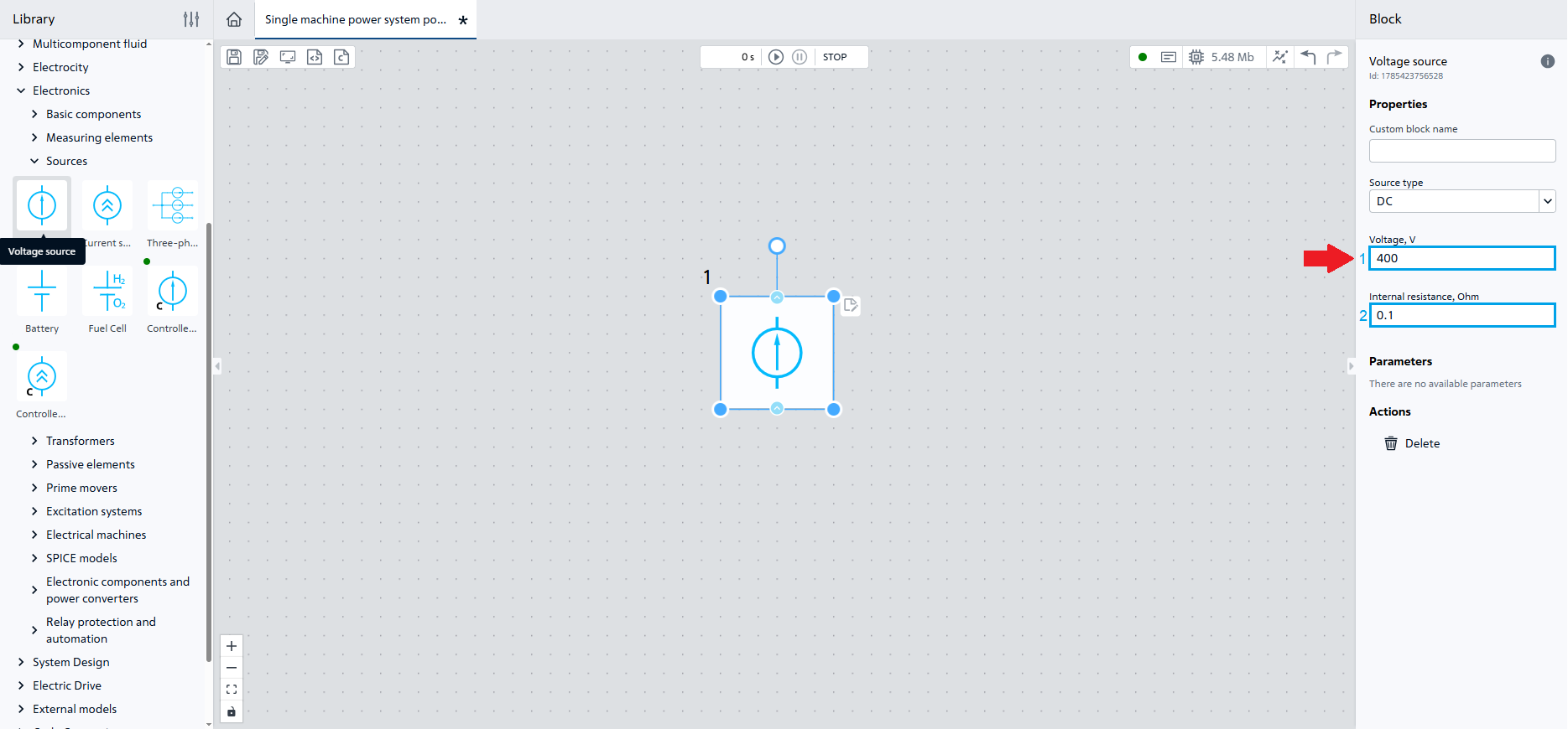
Fig. 2 Properties of block №1#
3. Inverter creation#
In order to simulate an inverter that is designed to convert direct current (DC) to alternating current (AC), transfer block №2 Full-bridge converter to the workspace.
Note
We leave the block properties unchanged.
Place and connect block №2 in accordance with the Fig. 3:
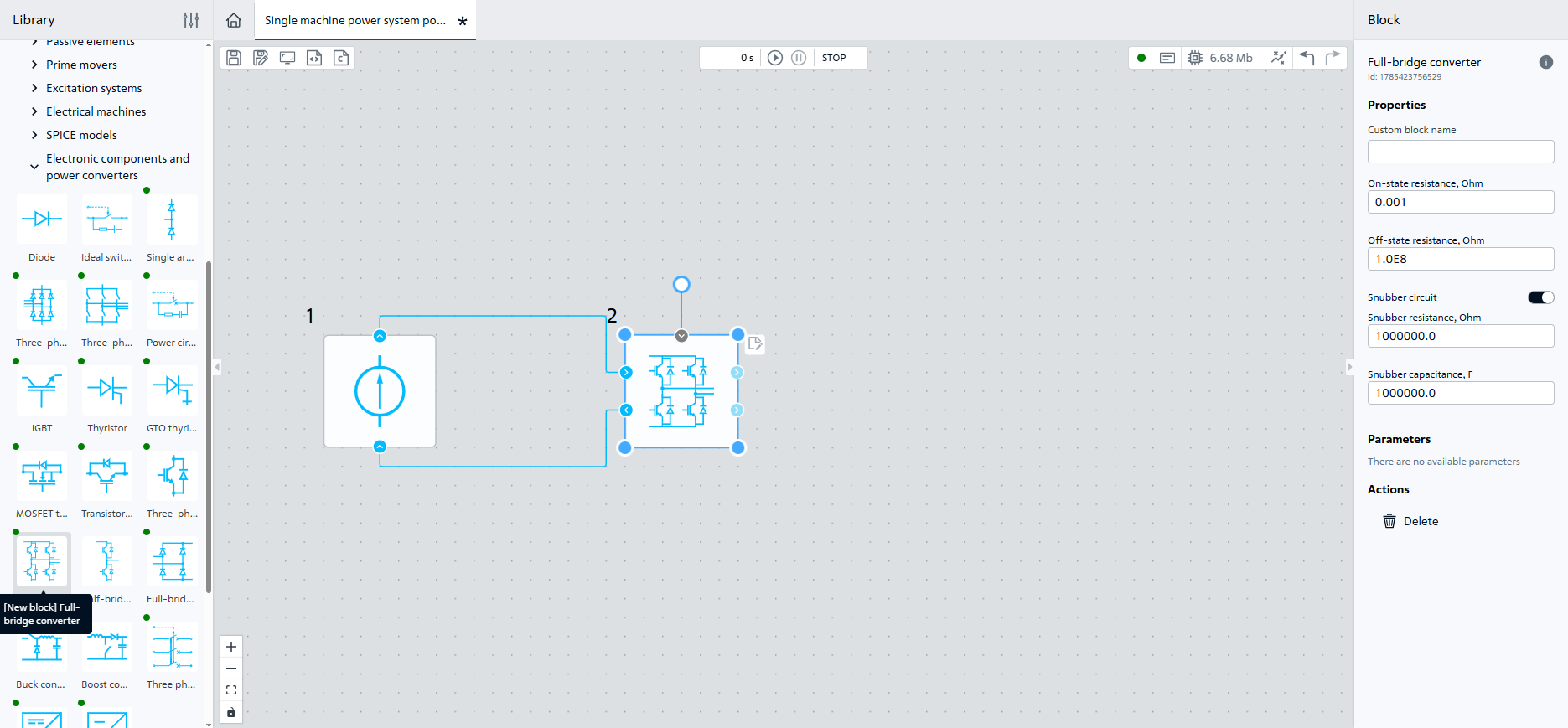
Fig. 3 Connection of block №2 to the diagram#
Hint
In order to improve the readability of the diagram by changing the position and shape of blocks connection, use the Function for changing joint position and shape.
4. Adding a resistor#
In order to simulate the active load resistance, transfer block №3 Resistor to the workspace.
Let’s set the Resistance property value for block №3 to 1 [Ohm], place and connect block №3 in accordance with Fig. 4:
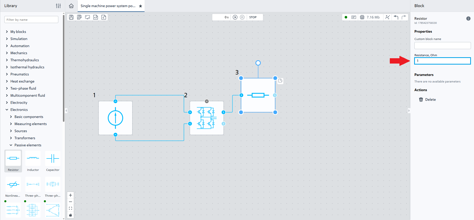
Fig. 4 Property of block №3 and its connection to the diagram#
5. Addition of inductance coil#
In order to simulate the reactive resistance of the load, transfer the block №4 to the workspace Inductor. We will specify the value of the Inductance property for it - 0.05 [H], and then place and connect the block in accordance with Fig. 5:
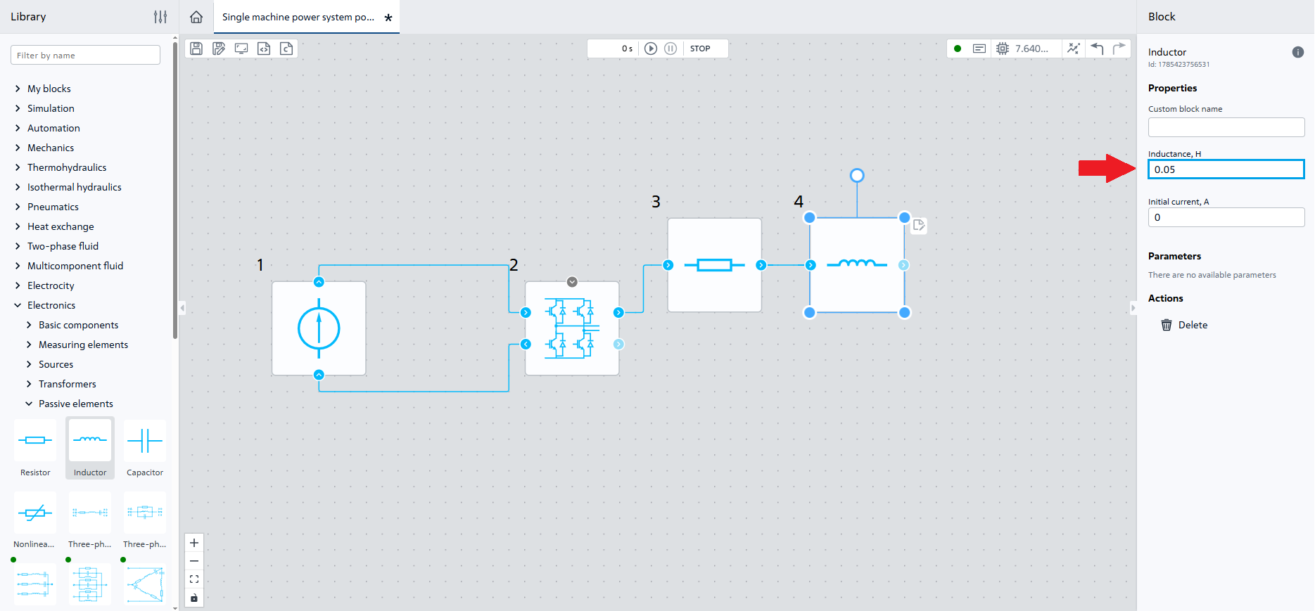
Fig. 5 Properties of block №4 and its connection to the diagram#
6. Adding a node#
In order to connect port 2 of block №2 Full-bridge converter to port - of block №4 Inductor add block №5 Node, for this purpose, transfer the block №5 of the same name to the workspace and specify the value of the Number of input ports property as 2, and then position and connect block №5 in accordance with Fig. 6:
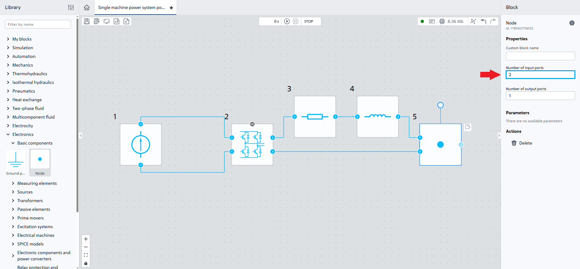
Fig. 6 Properties of block №5 and its connection to the diagram#
7. Addition of inverter control system#
In order to control block №2 Full-bridge converter it is necessary to supply pulses to its control port for switching the converter elements, for which move the block №6 Two level PWM generator to the workspace, set the following properties and then place and connect block №6 in accordance with the Fig. 7 below.
Value |
|
|---|---|
1 Bridge converter type |
2 arm bridge |
2 Modulation coefficient |
|
3 Carrier signal bias |
0 [s] |
Note
The rest of the properties of block №6 are left unchanged
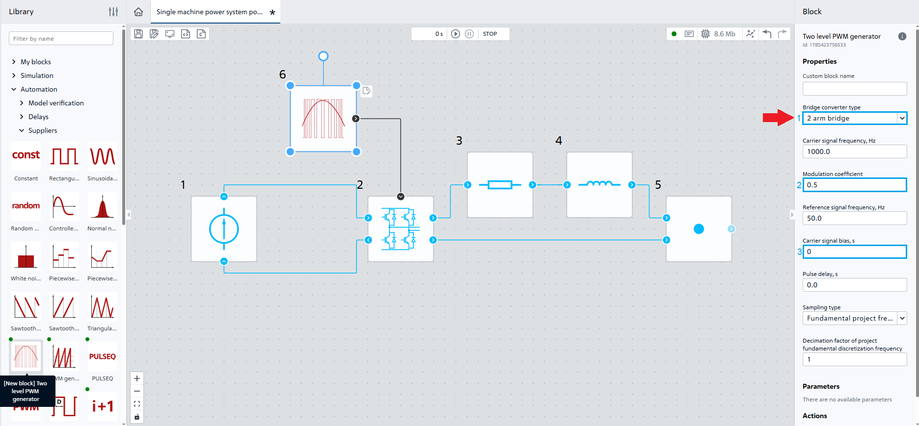
Fig. 7 Properties of block №6 and its connection to the diagram#
8. Adding sensors#
In order to display the load current and voltage signals, let’s add blocks №7-9 Meter. Specify the following property values for all three blocks Meter (see Fig. 8 below):
Element - Resistor;
Parameter -
Current, A.
Element - Resistor;
Parameter -
Voltage, V.
Element - Inductor;
Parameter -
Voltage, V.
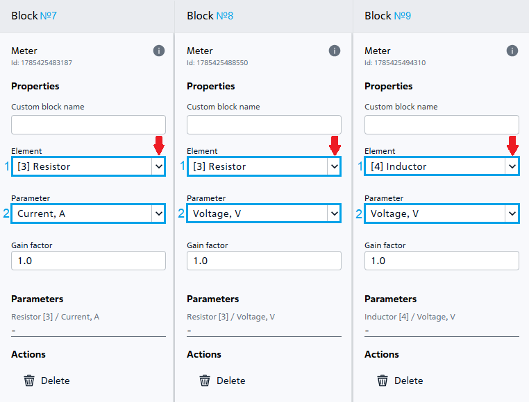
Fig. 8 Properties of blocks No. 7-9#
Place blocks №7-9 in accordance with the Fig. 9:
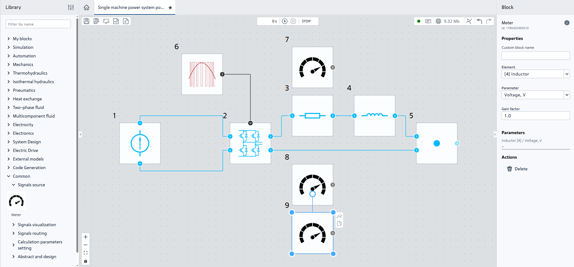
Fig. 9 Connection of meters#
9. Adding an adder#
In order to find the total value of the stress in a serial load connection, add the block №10 Addition (linear combination) to the workspace.
Note
We leave the block properties unchanged.
We place and connect block №10 in accordance with Fig. 10:
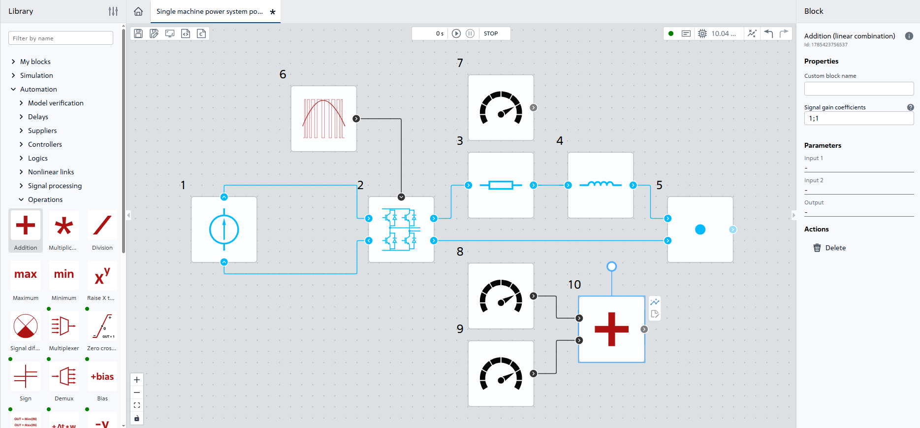
Fig. 10 Connecting block №10#
10. Adding RMS value#
In order to determine the effective value of voltage in the load circuit, add block №11 Root mean square to the workspace, set the following properties and then place and connect block №11 in accordance with the Fig. 11.
Value |
|
|---|---|
1 Initial RMS value |
220 |
2 Fundamental frequency |
50 [Hz] |
Note
Leave the rest of the properties unchanged.
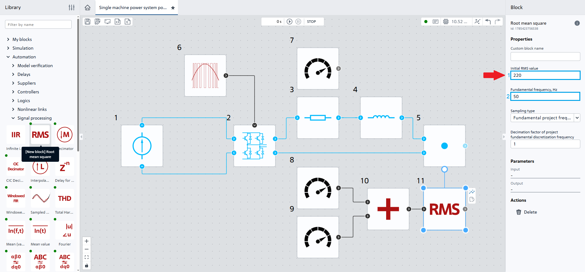
Fig. 11 Properties of block №11 and its connection to the diagram#
11. Add charts for visualization#
Go to the
Visualizationtab (see Fig. 12 below);Add three charts by triple clicking on the button Add located in the right lower corner.
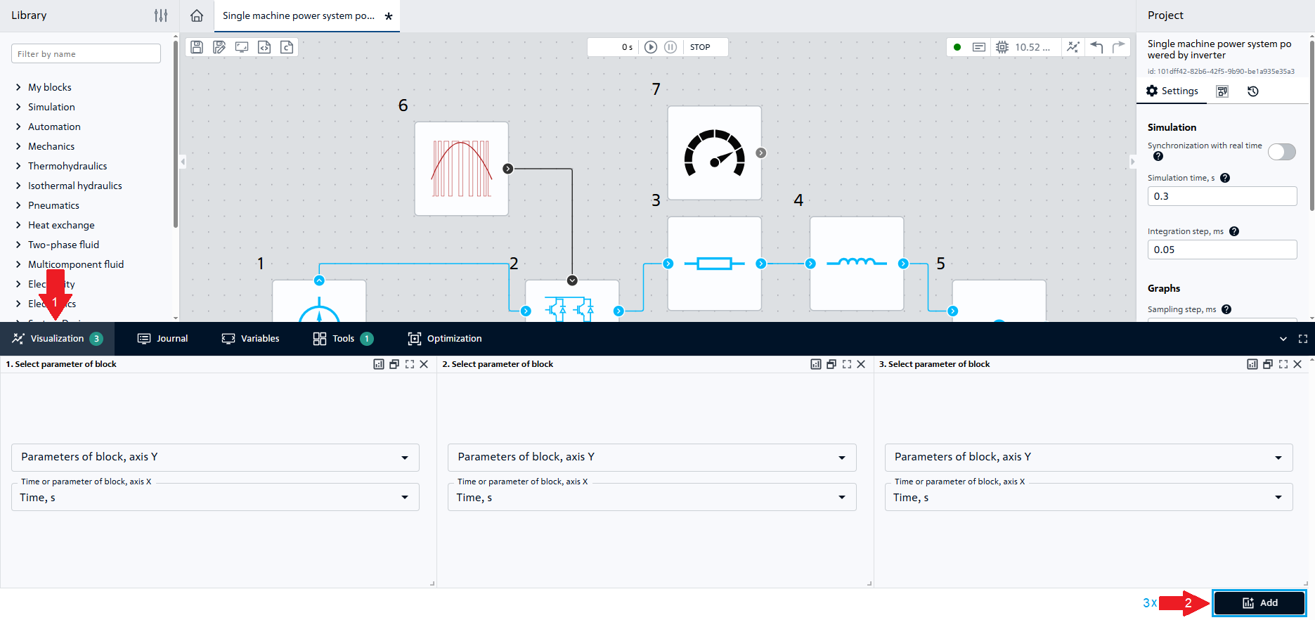
Fig. 12 Visualization#
Then you need to perform two steps to add each chart (see Fig. 13 below):
Add one chart to display the data of block №7;
Add second chart to display the data of block №10;
Add third chart to display the data of block №11.
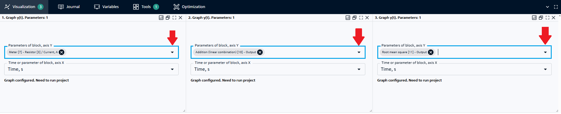
Fig. 13 Adding charts#
Start calculation using the “Start simulation”  button
The calculation should be successfully completed with the following message:
Modeling stopped on the solver side due to modeling time limit exceeded.
The previously created charts should now display the calculation results, which are shown in the Fig. 14, Fig. 15, Fig. 16.
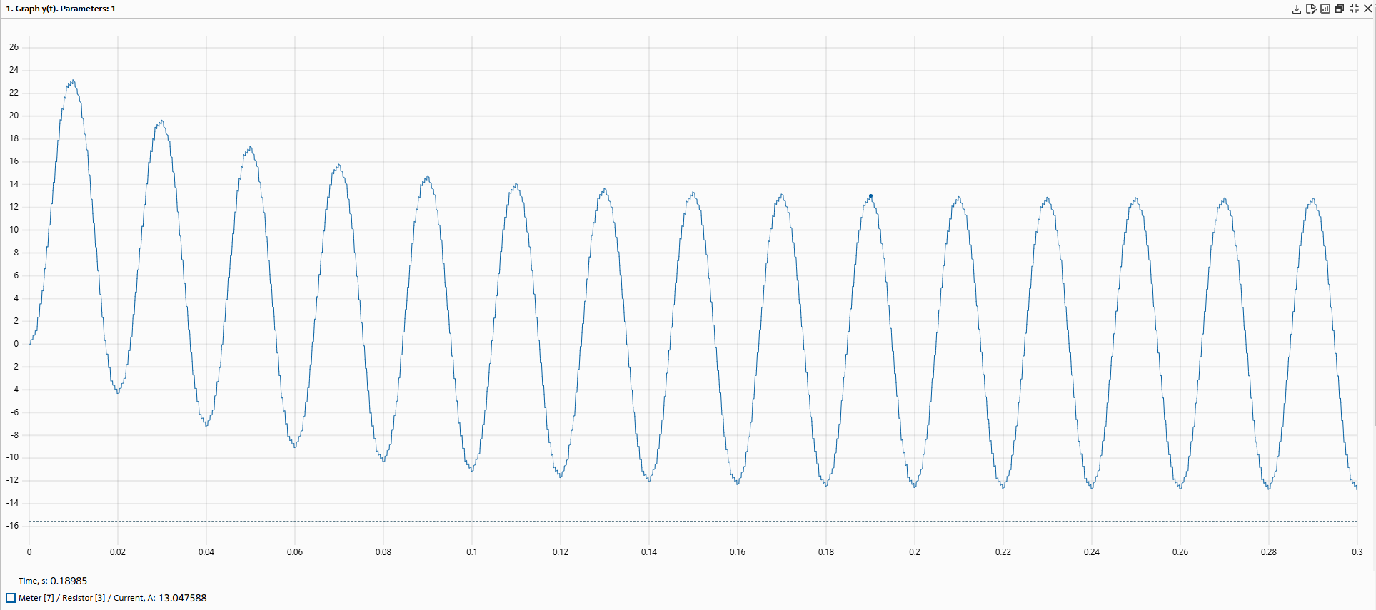
Fig. 14 Chart 1#
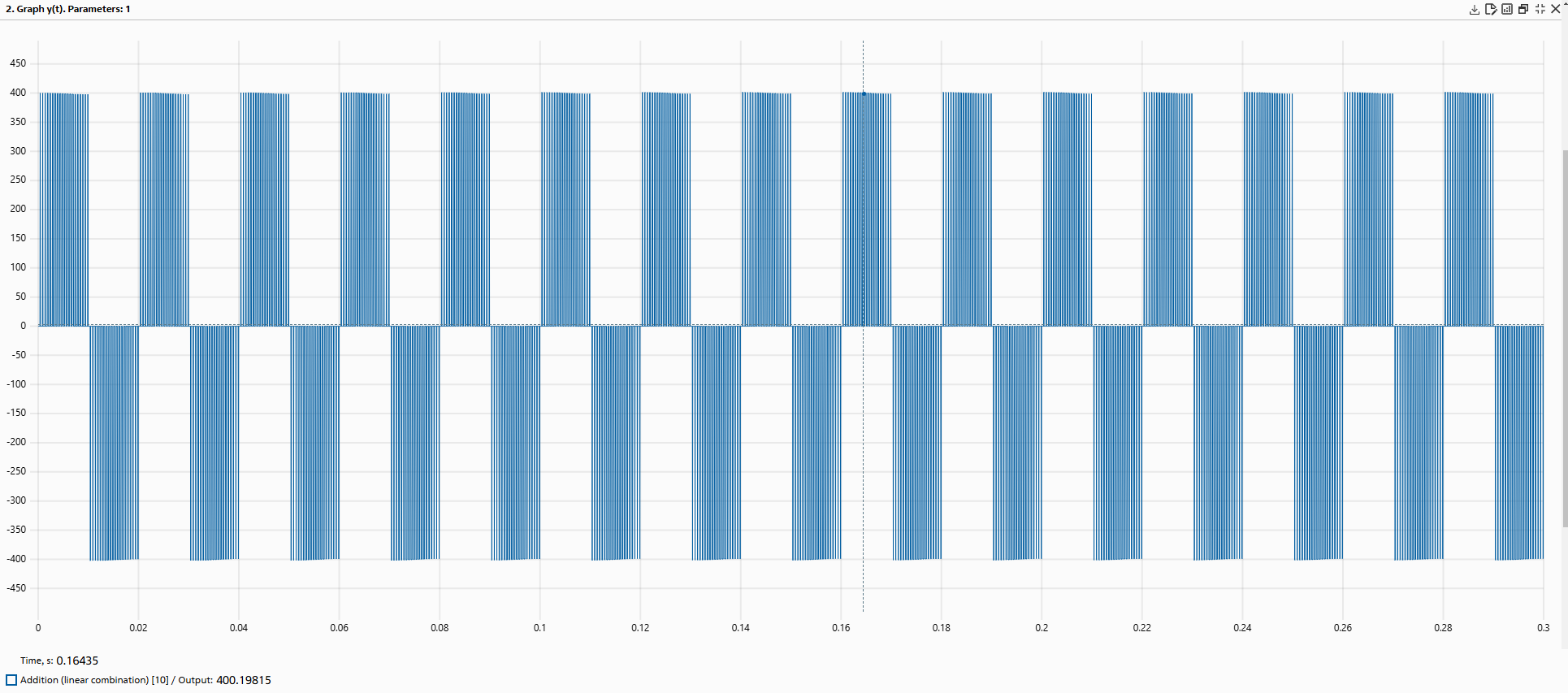
Fig. 15 Chart 2#
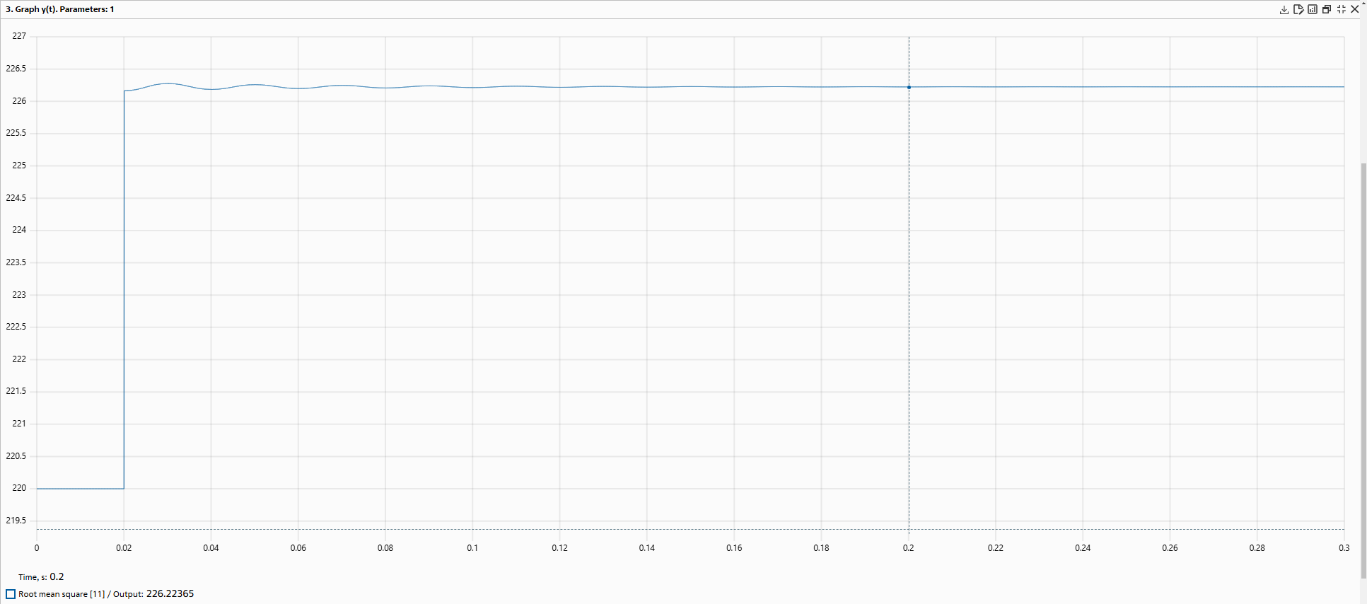
Fig. 16 Chart 3#
12. Analysis of calculation results#
The simulation results correspond to theoretical relationships, since the current in the circuit after the converter is sinusoidal, the type of voltage curve also repeats the sinusoid taking into account pulse-width modulation. The effective value of voltage in the load circuit is approximately 226 [V], since in block №6 Two level PWM generator, a modulation factor of 0.5 is set to reduce the inverter input voltage.
13. Conclusions#
In this tutorial, you learned how to model a single-phase network with an inverter.
You have learned how to:
set parameters of blocks Voltage source; Full-bridge converter; Resistor; Inductor; Two level PWM generator; Root mean square;
use block Meter to display block signals;
use block Root mean square to find the actual value of the sinusoidal signal.