

Pipeline between two reservoirs#
This tutorial describes simple steps to customize the circuit to solve an isothermal hydraulics problem.
In this tutorial we consider a problem in which the model boundary conditions will be gauge pressure parameters in reservoirs, and as a calculation result it is required to determine the flow rate of liquid in the pipeline.
1. Project creation and customization#
Firstly, it is necessary to create a new project and give it a name, e.g. Pipeline between two reservoirs.
The next step is to configure Simulation time, by assigning a value of 1 second to the corresponding project parameter, Fig. 1:
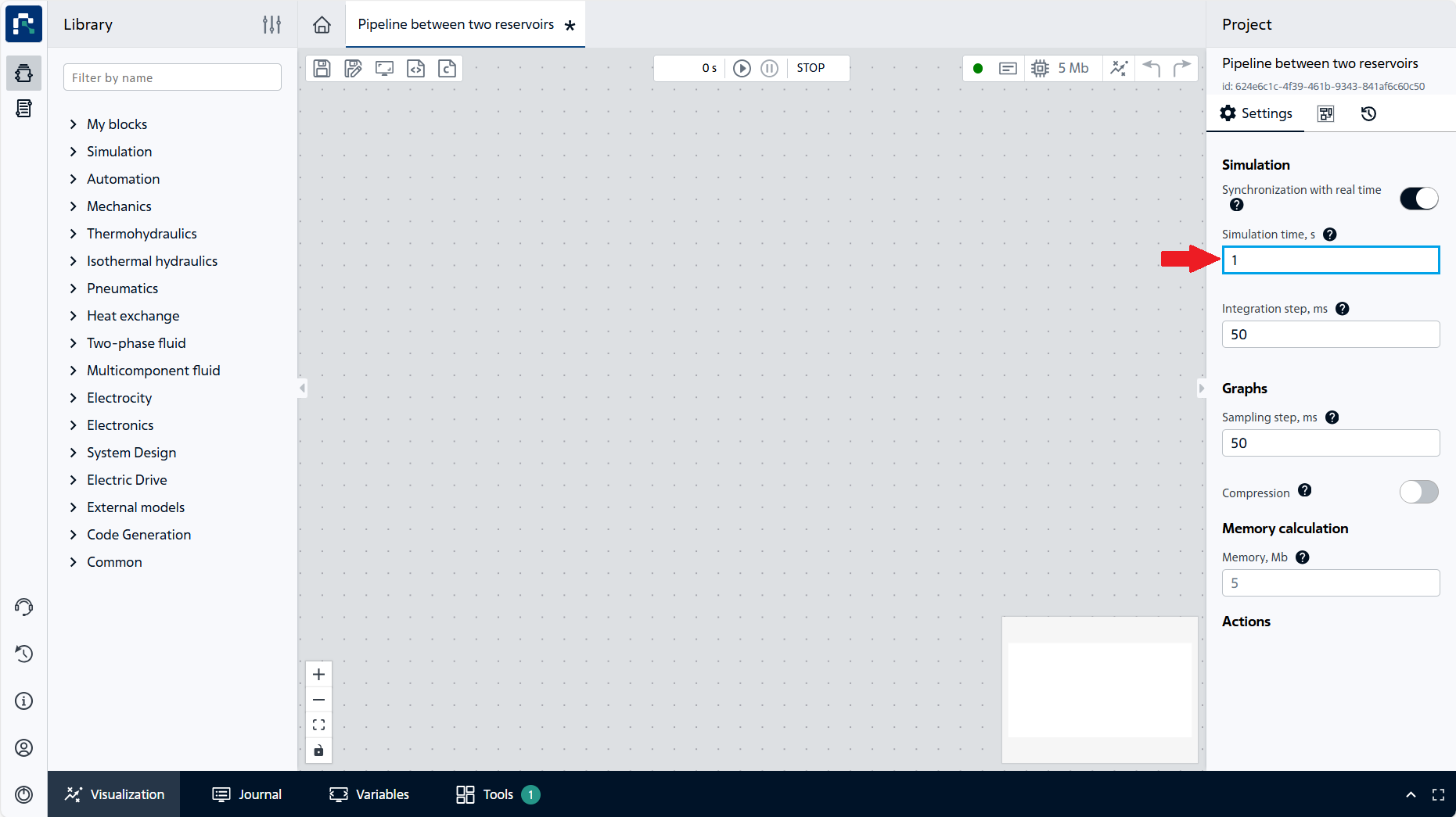
Fig. 1 Setting the simulation time#
Start to perform basic steps to create a hydraulic model by opening Isothermal hydraulics library.
2. Reservoirs creation#
Add the first block of our model (see Fig. 2 below), by moving Reservoir (IH) block to the working area to apply pressure as a boundary condition of the model.
Assign a value of 50000 [Pa] to Gauge pressure parameter in settings of the first block.
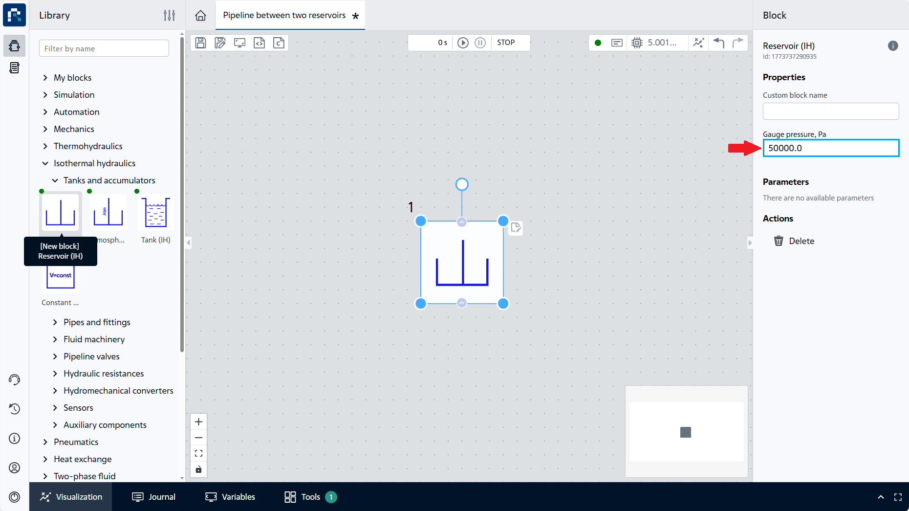
Fig. 2 Adding the Reservoir block#
Then it is necessary to add the same tank to the working (see Fig. 3 below) area and assign Gauge pressure parameter of the second unit the value 0 [Pa].
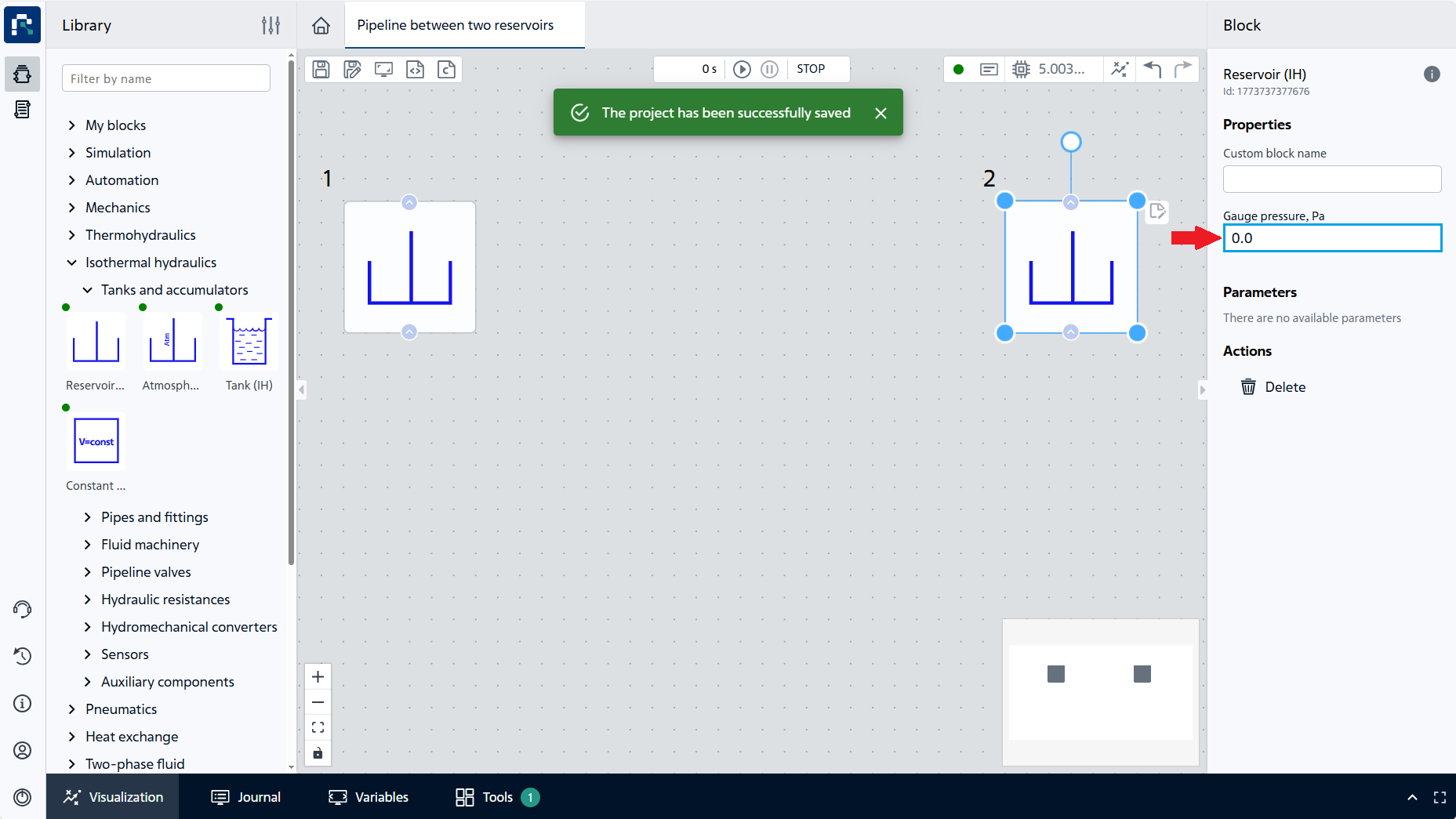
Fig. 3 Adding and configuring the second Reservoir block#
As a result, the project is ready to add a pipe section. Save the project and continue with the following steps.
3. Pipe creation#
To link the tanks together, add a Pipe (IH) (see Fig. 4 below). Drag the block of the same name to the workspace and assign the following property values:
Important
In REPEAT VISION decimal numbers are specified through a period.
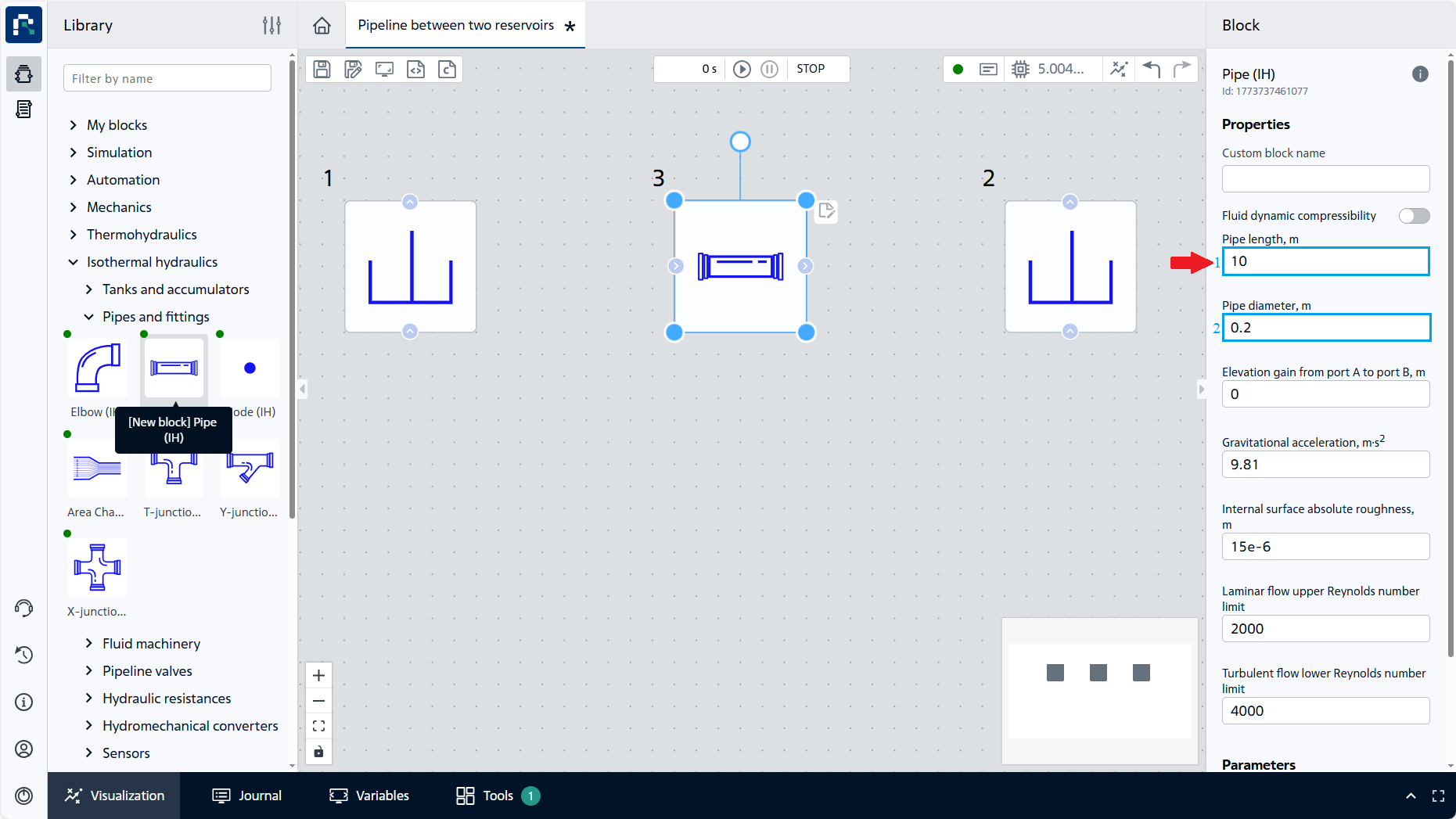
Fig. 4 Adding the Pipe (IH) block#
Then connect the blocks according to the Fig. 5 given below:
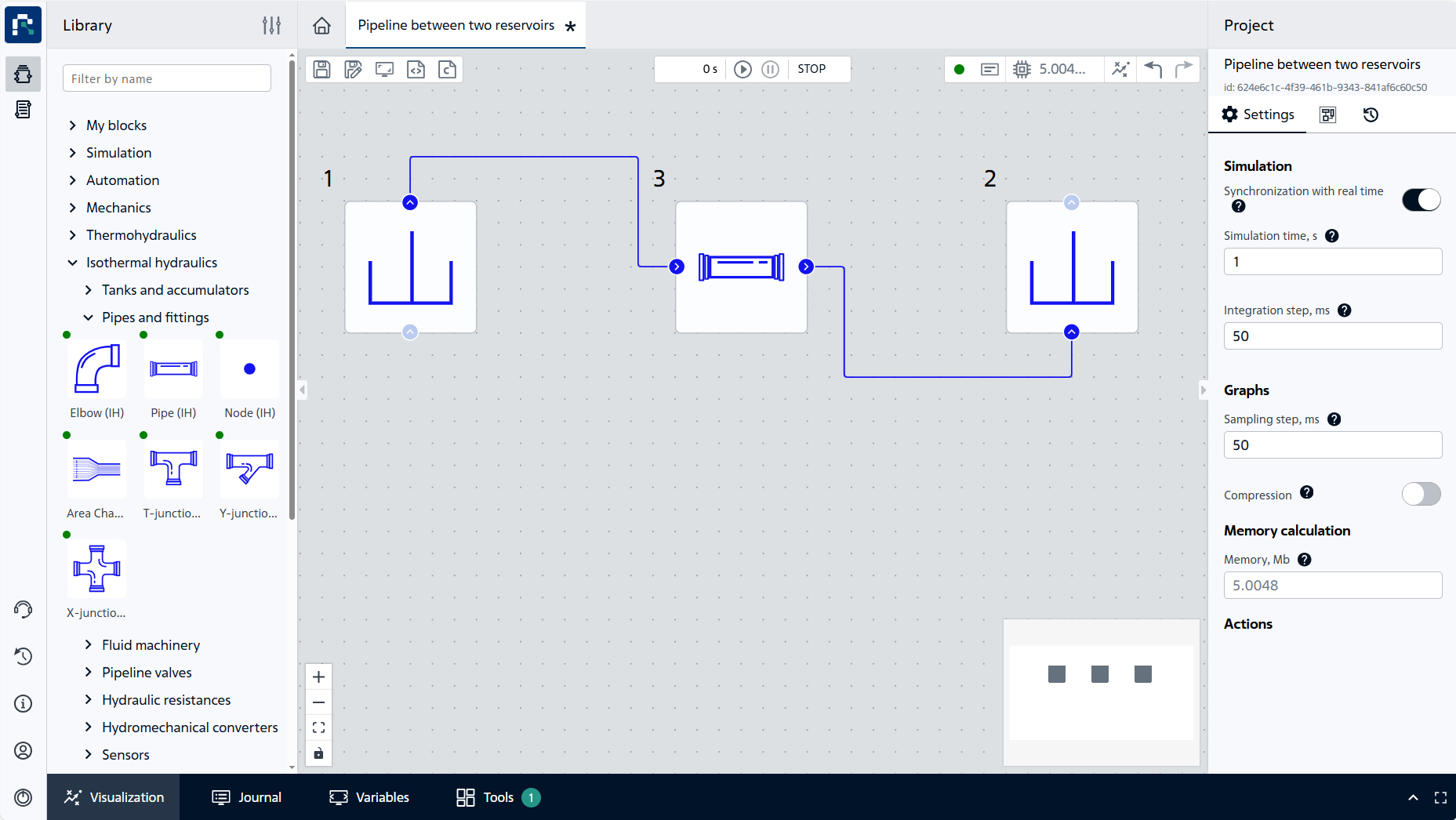
Fig. 5 Connecting blocks#
The following links shall be configured on the scheme as a result:
Outputof block 1 is connected withinputof block 3Outputof block 3 is connected withinputof block 2
4. Setting fluid properties#
Add the fourth block to the working area. From Isothermal hydraulics library it is necessary to move Isothermal liquid properties (IH) block, and also to specify the following properties (see Fig. 6 below):
From
Related blockdrop-down list, it is necessary to select the value [1] Reservoir;From
Parameterdrop-down list, it is necessary to select the value Output.
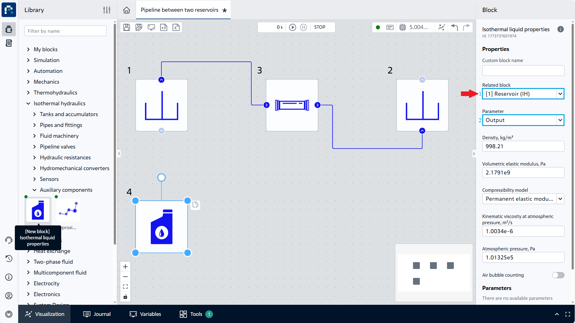
Fig. 6 Adding and configuring the Isothermal liquid properties block#
Important
Isothermal liquid properties (IH) is a mandatory block of all schemes for isothermal hydraulic simulation.
5. Selecting the required types of calculation results#
To determine the flow rate in a pipeline section, add the last block in this tutorial - Flow sensor (IH) (see Fig. 7 below), in the drop-down list of its properties, select the interested block [3] Pipe.
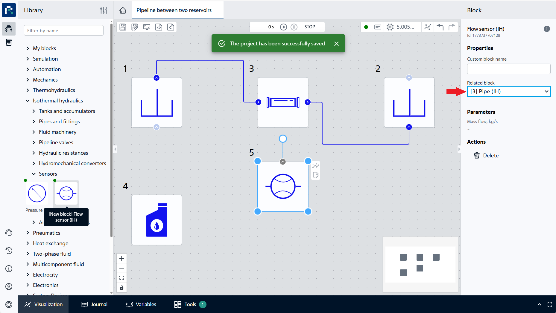
Fig. 7 Adding the Flow sensor block#
The hydraulic model is ready for the calculation. Save the project and continue to the step to start the model for calculation.
6. Starting the calculation#
Start the calculation using the Run simulation button 
The calculation shall successfully complete with the following message:
Modeling stopped on the solver side due to modeling time limit exceeded.
7. Analysis of calculation results#
After successful completion of calculation in Flow sensor (IH) block there will be indicated flow rate at the moment of model time completion. The value of Mass flow parameter shall be equal to 403.68 [kg/s], Fig. 8:
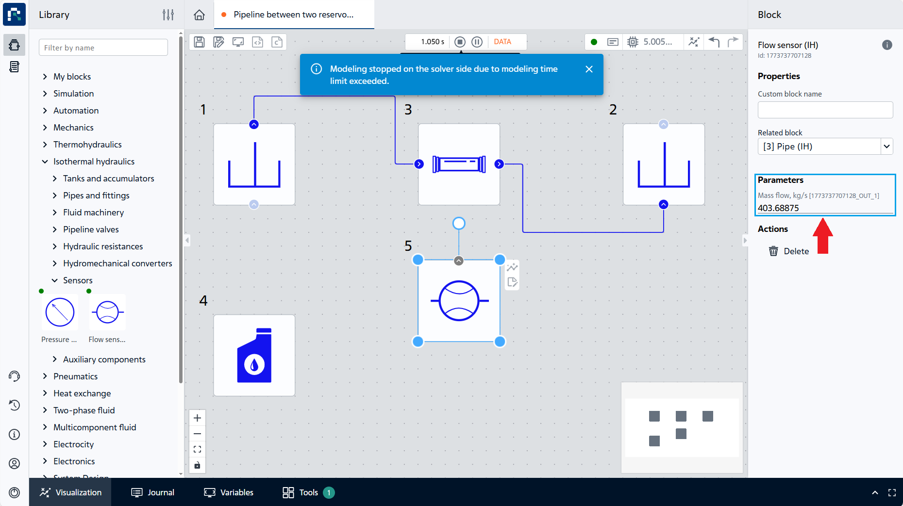
Fig. 8 Obtaining calculation results#
8. Conclusions#
As a result of this tutorial, you have learned the basic knowledge to solve a hydraulic problem. You have learned:
Create hydraulic model boundary conditions of overpressure type using block Reservoir (IH);
Determine the liquid flow rate as a calculation result using block Flow sensor (IH);
Configure fluid properties using the Isothermal liquid properties (IH) block.