

Inductance in DC circuit#
This tutorial describes simple steps to create a DC electrical circuit with a resistor and inductance coil.
In this tutorial, you learn how to simulate transient processes in a DC circuit when an inductance coil is activated. As a calculation result, it is required to determine magnitude of current and voltage in the circuit before and after inductance coil activation.
1. Create and set up a project#
First, it is necessary to create a new project and give it a name, for example, Inductance in a DC circuit.
In the next step, it is necessary to (see Fig. 1 below):
Disconnect the
Synchronization with real timeoption, so that it is possible to set the simulation time < 1 [s];Set the
Simulation timebysetting a value of 0.2 [s] to the corresponding project parameter;Configure the
Integration stepbysetting a value of 0.05 [ms] to the corresponding project parameter;Adjust the
Sampling stepbysetting a value of 0.05 [ms] to the corresponding project parameter.
Important
In REPEAT VISION decimal numbers are separated by a dot.
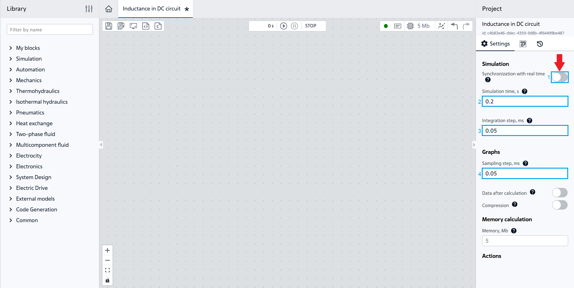
Fig. 1 Project setup#
Let’s start to perform basic steps to create a circuit by opening the Electronics library.
2. Creating a voltage source#
Let’s add the first block of our circuit (see Fig. 2 below), for this purpose move the Voltage source` block to the working area to power the DC circuit.
The following shall be done in properties of the first block:
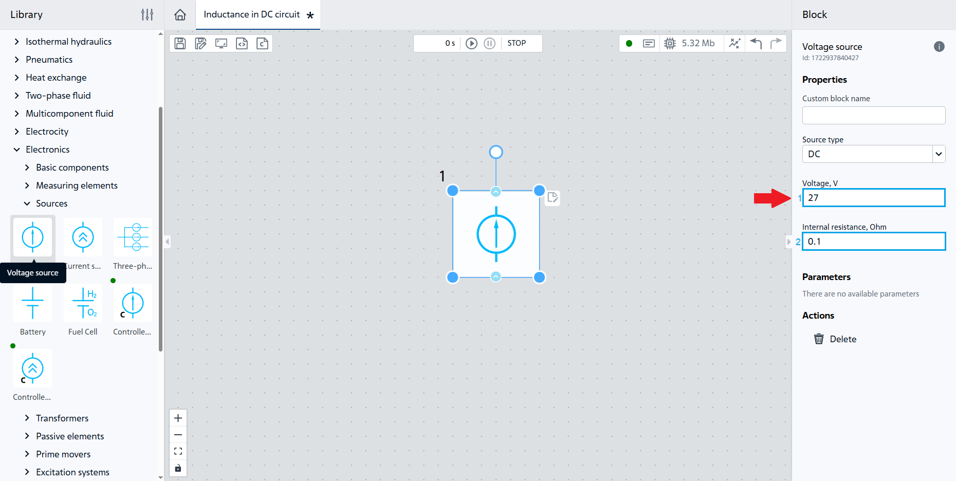
Fig. 2 Adding and configuring the Voltage source block#
As a result, the project is ready to add Nodes. Save the project and continue with the next steps.
3. Creating nodes#
To be able to connect a voltmeter and create a parallel circuit, we will add a Node block. To do this, we need to move the block of the same name to the working surface, then rotate the block 90\(^0\) to the left for further convenience of constructing the circuit and specify the value of the Number of output ports property as 2 (see Fig. 3 below).
Then it is necessary to copy the Node block by selecting it (click on the block with the LMB) then CTRL+C, CTRL+V commands.
After that, add the third Node block to the work are with the following properties (see Fig. 3 below):
Number of input ports- 2;Number of output ports– 2.
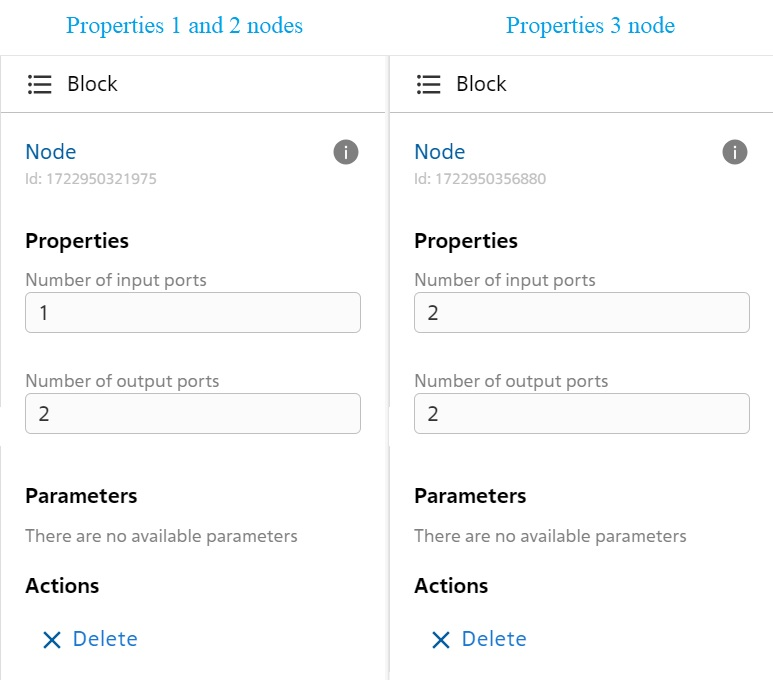
Fig. 3 Configuring Node blocks#
Place and connect the blocks in accordance with the Fig. 4:
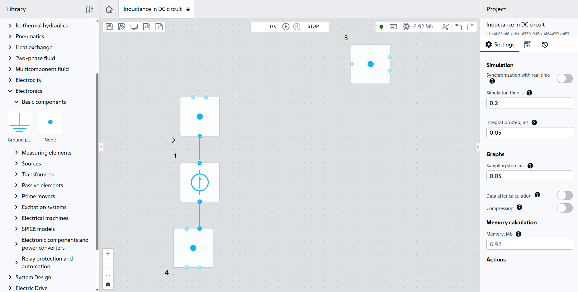
Fig. 4 Placement and connection of Node blocks#
We save and move on to adding measuring elements.
4. Adding measuring components#
To measure the parameters of the circuit, we add three Current meter blocks, and a Voltage meter, which must be rotated 90\(^0\) to the right (see note under the graph).
Place and connect the blocks in accordance with the Fig. 5:
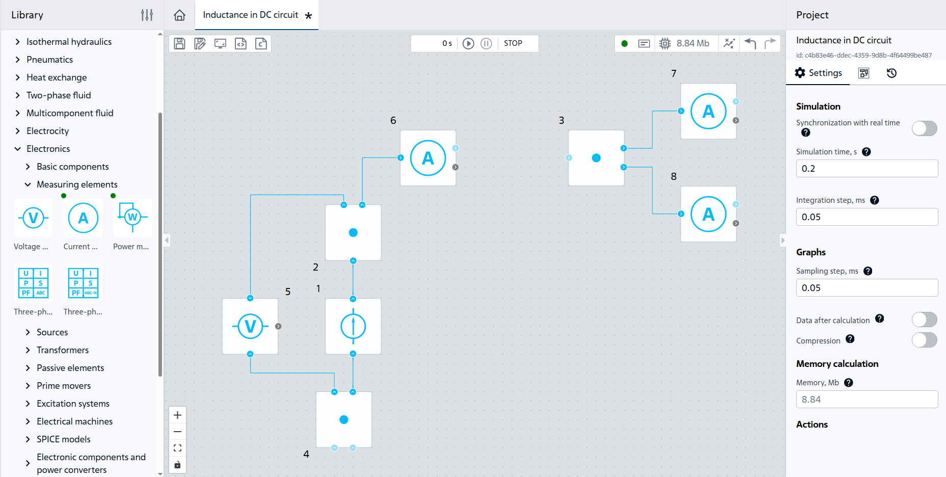
Fig. 5 Adding and connecting measuring elements#
Important
In order to obtain correct voltmeter readings, the “+” input of the voltmeter and the “+” output of the voltage source shall be connected to the same assembly, similarly, the “-” input of the voltmeter and the “-” input of the voltage source shall also be connected to the same assembly. Otherwise, the result will be a negative voltage.
5. Creating resistors#
Add Resistor blocks to set resistances. Move the block №9 (see Fig. 6 below) to the working area, in its properties indicate the resistance value - 1.5 [Ohm]. Then move another block №10 (see Fig. 7 below) of the resistor to the working area, and indicate the resistance value - 5 [Ohm], turn it 90\(^0\) to the right for further convenience in creating the circuit.
Then connect the blocks in accordance with the figures (Fig. 6 and Fig. 7) showing the placement of the resistors (blocks №9 and №10).
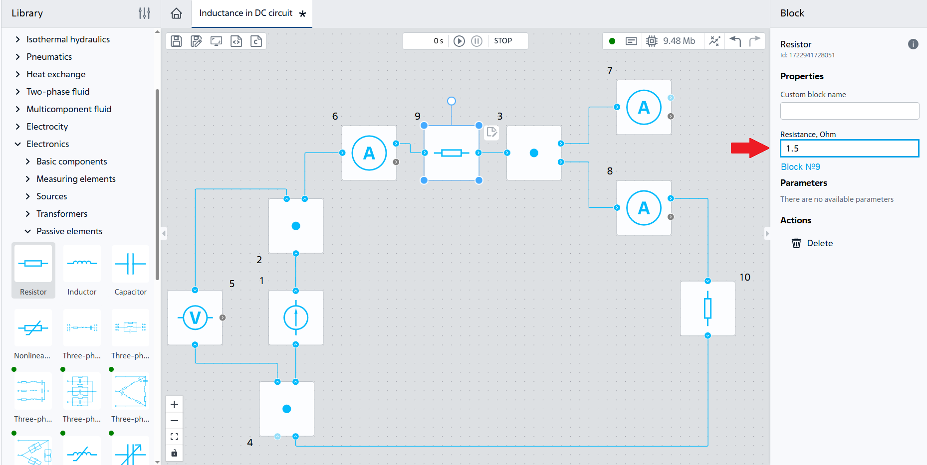
Fig. 6 Adding block №9#
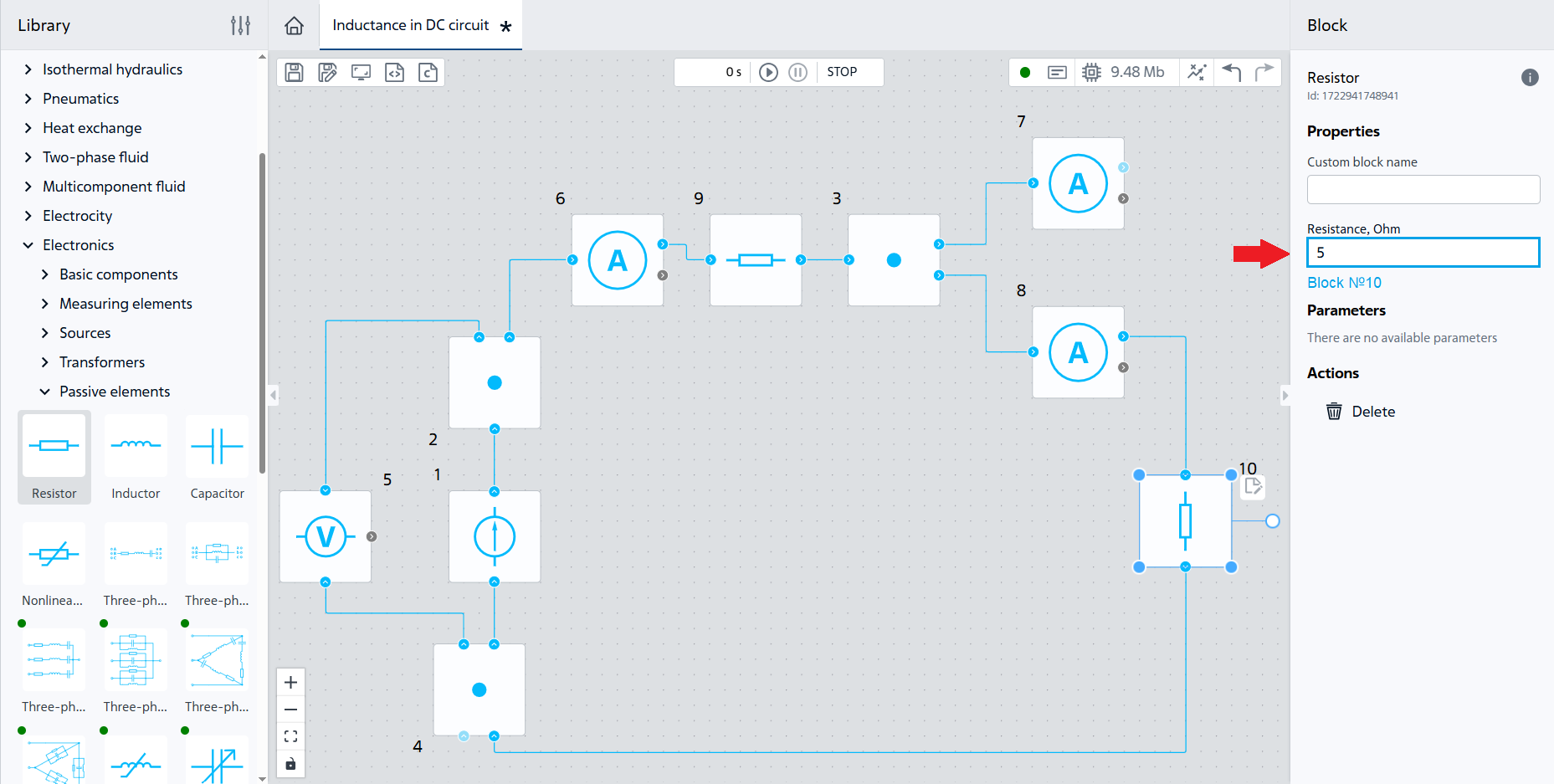
Fig. 7 Adding block №10#
6. Creating an inductance winding#
In order to accumulate energy from the magnetic field, move the Inductor block to canvas and turn it 90\(^0\) to the right for the convenience of creating a diagram. Set the value of the Inductance property – 0.005 [H].
Place and connect the block in accordance with the Fig. 8:
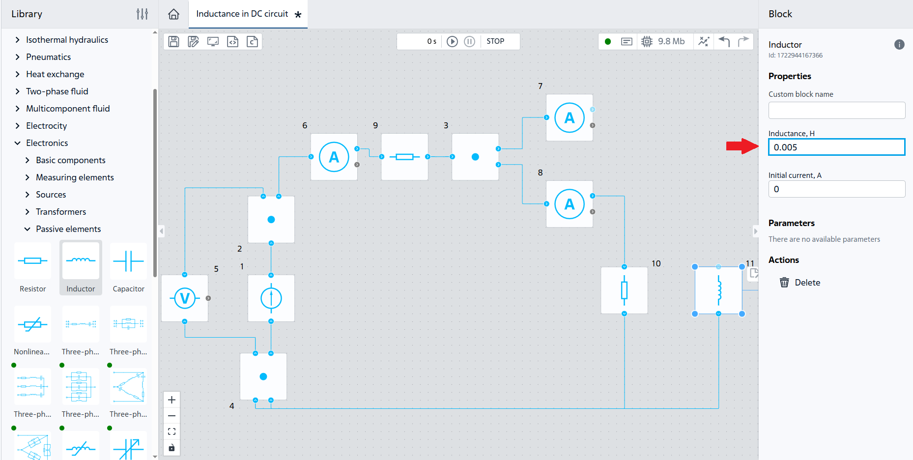
Fig. 8 Adding and connecting the Inductor block#
7. Add the perfect key#
Move the Ideal switch block to canvas. In block properties, disconnect Snubber circuit option, other parameters remain unchanged.
Place and connect the block in accordance with the Fig. 9:
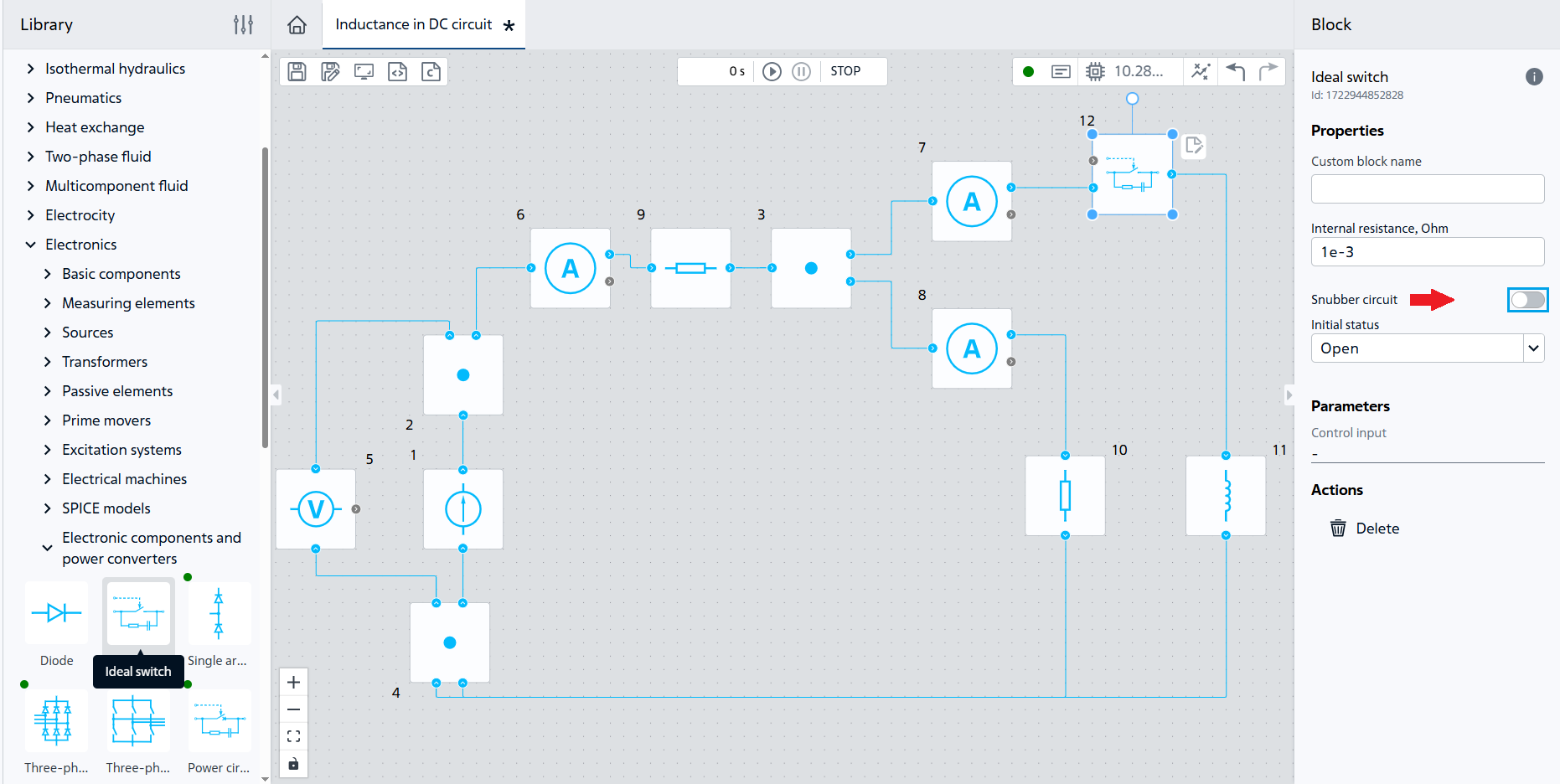
Fig. 9 Adding and connecting the Ideal switch block#
8. Creating a permanent piecewise function#
In order to control the ideal switch, it is necessary to add Piecewise constant function block (from Automation section in Suppliers tab). Move it to canvas and set the following values in the block properties:
Vector of time arguments: 0; 0.1;Vector of function values: 0;1Periodicityoption: disconnect.
The set parameters will allow to get a function that:
in time interval from 0 to 0.1 [s] takes the value 0;
from 0.1 [s] to 0.2 [s], the value of the function will be 1.
Place and connect the block in accordance with the Fig. 10:
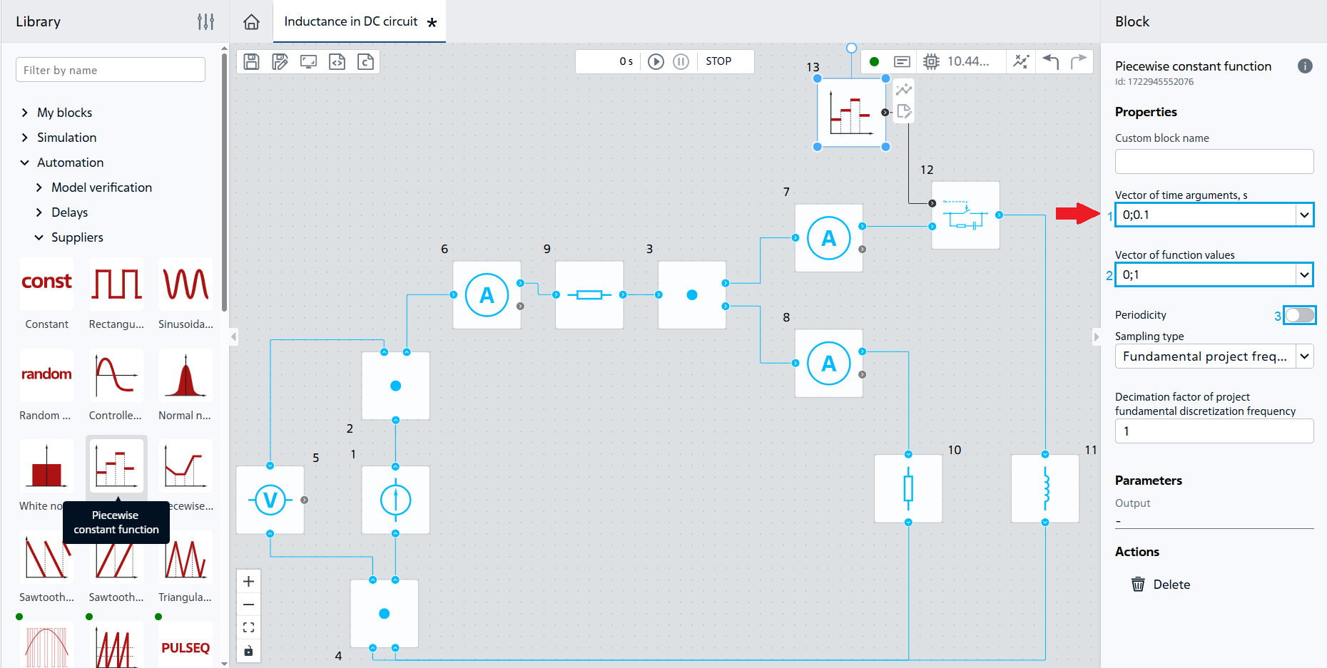
Fig. 10 Connecting and configuring the Piecewise constant function block#
9. Add graphs for visualization#
Go to the Visualization tab:
Add one graph to display the voltage meter signal;
Add the second graph to display the signal of three current meters, Fig. 11:
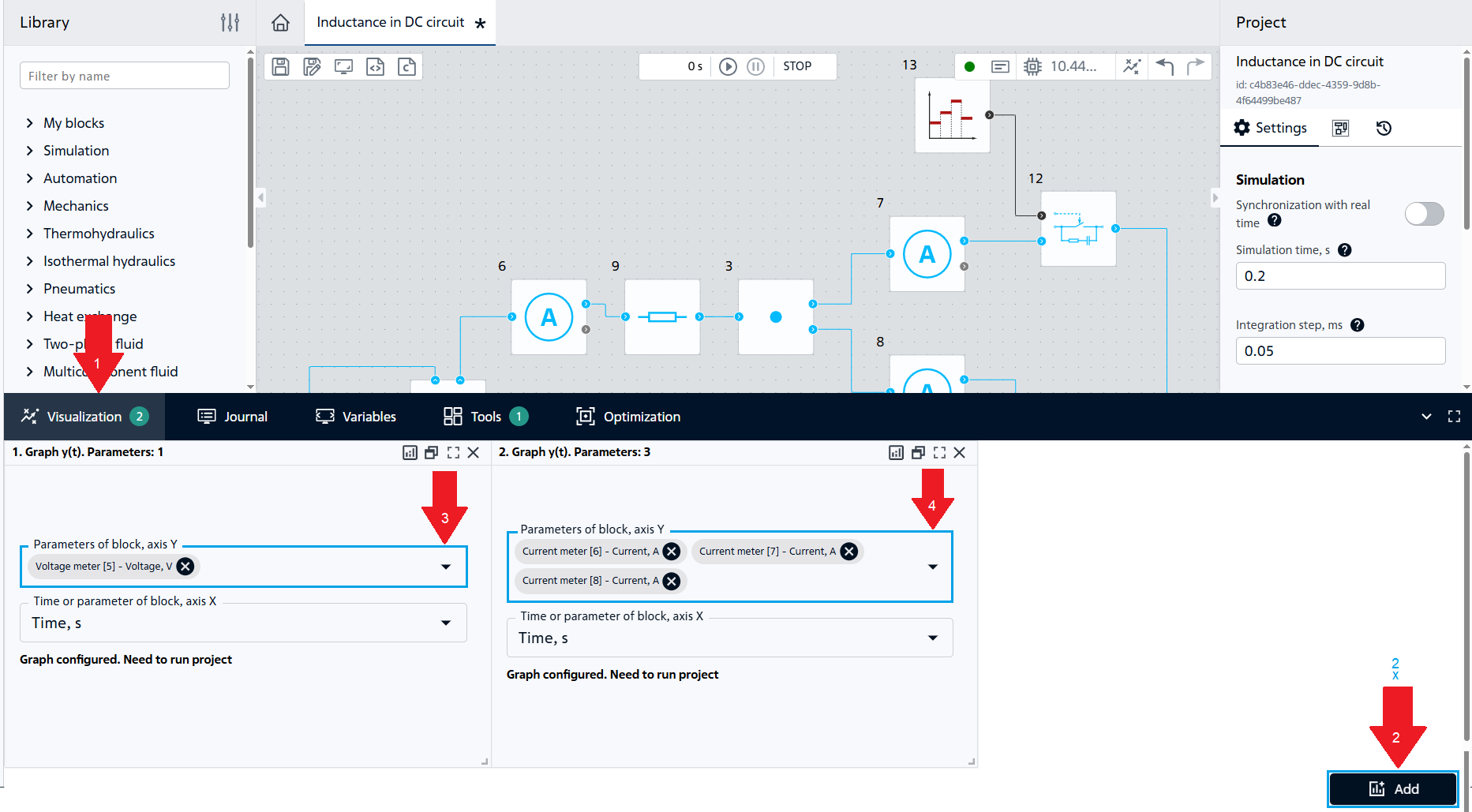
Fig. 11 Adding graphs#
Start the calculation with “Start Simulation” button 
The calculation shall be successfully completed with the following message:
Modeling stopped on the solver side due to modeling time limit exceeded.
The resulting circuit operates as follows - in the time interval from 0 to 0.1 [s], the current from the voltage source flows through the resistors (blocks 9 and 10), Fig. 12:
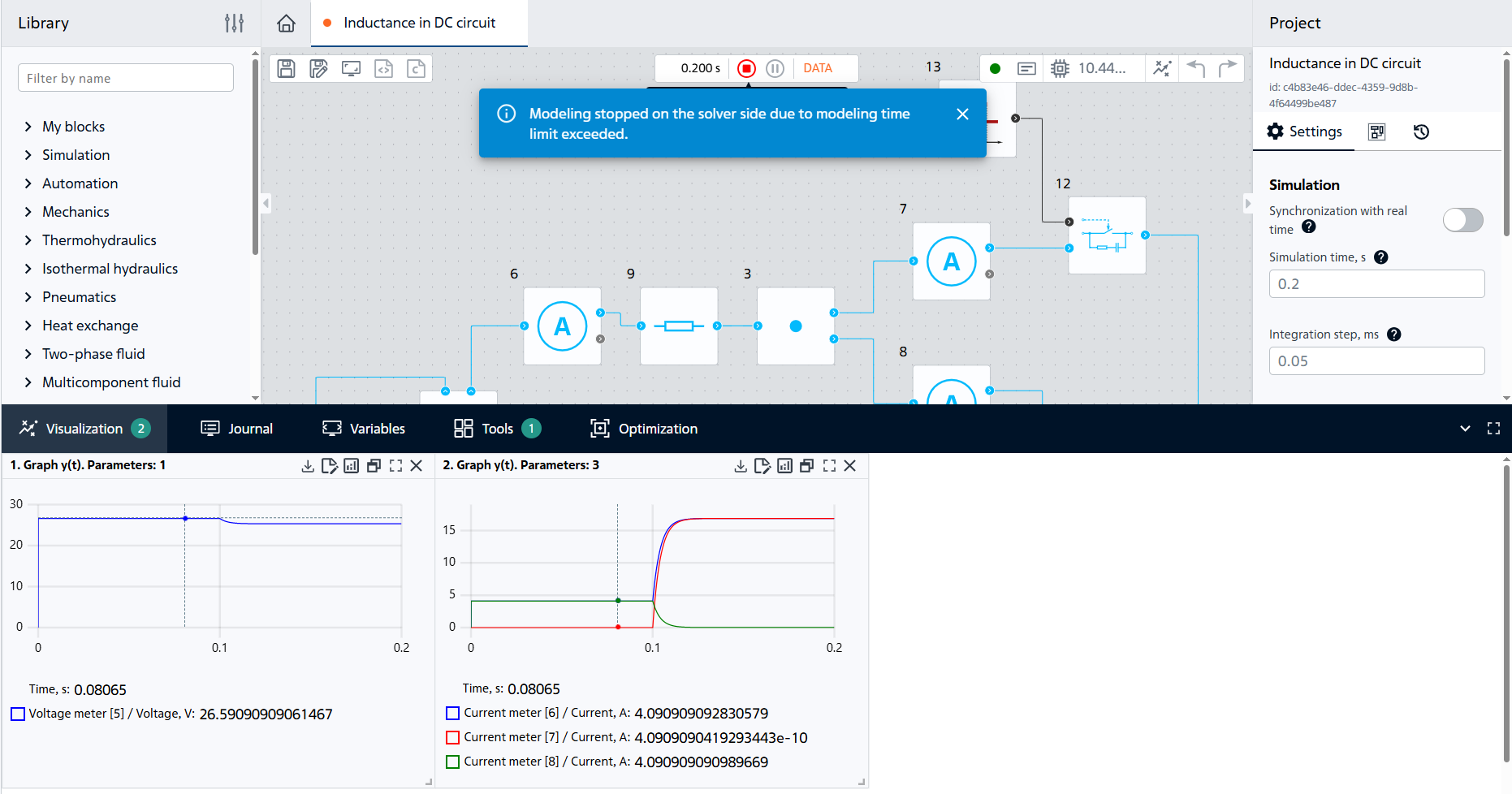
Fig. 12 Circuit operation in the range from 0 to 0.1 [s]#
After 0.1 [s], the switch block №12 is closed and current begins to flow also through the inductance winding block №11, Fig. 13:
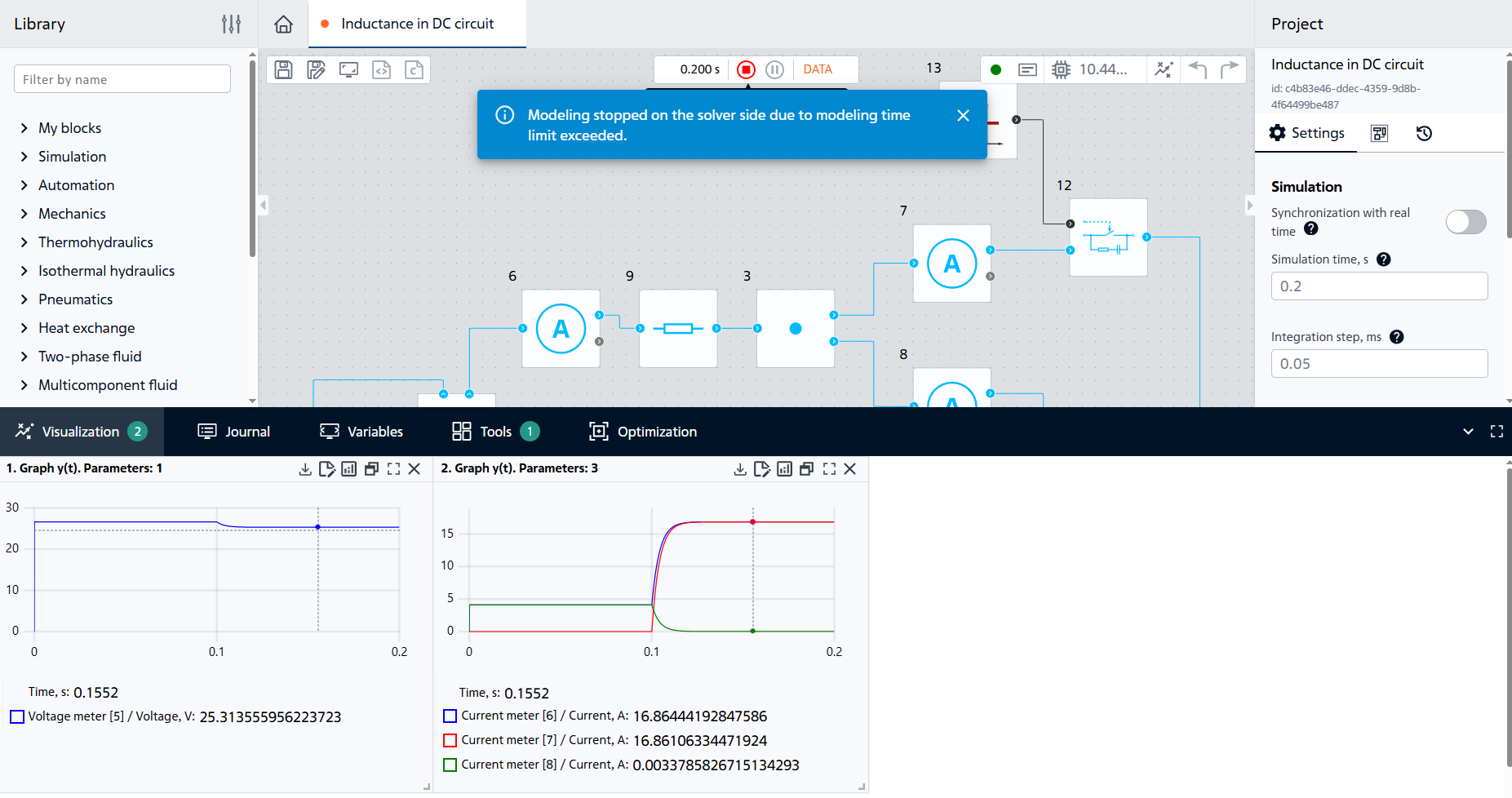
Fig. 13 Circuit operation after 0.1 [s]#
10. Analysis of calculation results#
The simulation results correspond to theoretical dependencies - the Inductor in DC circuit does not resist the flowing current. Therefore, when the switch is closed, the current passes from resistor (block №10) to coil (block №11), and the current in the unbranched part of the circuit increases approximately 4 times - from 4.1 [A] to 16.9 [A] (readings of [Current meter`](../../../../reference/blocklib/electronics/measuringElements/ElectronicCurrentMeter/index.md) block №6). In this case, the current through the inductance coil increases gradually due to the self-induction phenomenon. The source voltage decreases from 26.6 [V] to 25.3 [V] after the inductance is connected, due to increase in current in the circuit and increase in voltage losses on its internal resistance.
11. Conclusions#
In this tutorial, you learned the basics of creating a DC electrical circuit with a resistor and inductance coil. You have learned:
Set parameters of the blocks Inductor, Ideal switch, Piecewise constant function.
Use the Ideal switch block to change the circuit configuration.
Use the Piecewise constant function block to control the state of the Ideal switch block