

Thyristor#
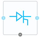
Block appearance in REPEAT VISION#
The Thyristor block is a simplified model of thyristor. The equivalent circuit of such thyristor consists of a key that determines the thyristor resistance (it is equal to internal resistance at activation, and equal to resistance in the closed state at deactivation) depending on the logic signal and voltage between the anode and cathode. It is necessary that 1 is sent to the control electrode and voltage between the anode and cathode is greater than \(U_f\) to open. Then the signal magnitude is unimportant as the thyristor will remain open until voltage between anode and cathode decreases to \(U_f\) or lower. The equivalent circuit of thyristor and its CVD is given in figures below (Fig. 1) and (Fig. 2).
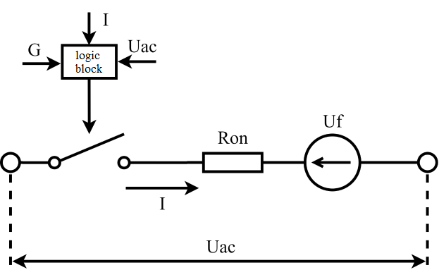
Fig. 1 Thyristor equivalent circuit#
In this circuit:
G - control signal (can take a value equal to either 0 or 1; 0 corresponds to the closed position of the thyristor and 1 to the open position);
I - value of thyristor current, [А];
\(U_{ac}\) - voltage between anode and cathode, [V];
\(R{on}\) - resistance of thyristor in open state, [Ohm];
\(U_f\) - forward bias voltage of transistor p-n movement, [V].
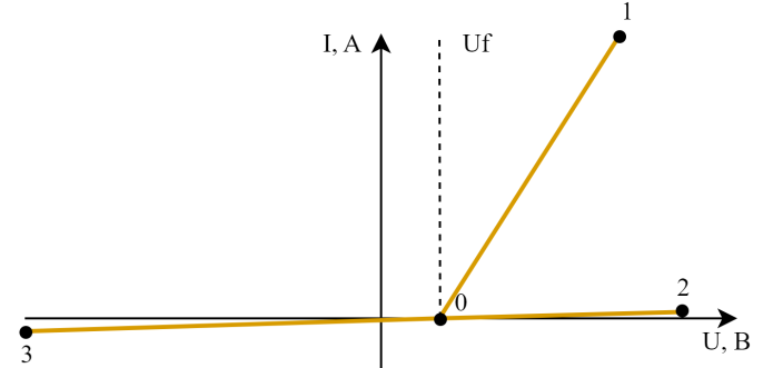
Fig. 2 Thyristor CVD#
The thyristor CVD reflects logic of its operation. So, when voltage is applied between the anode and the cathode, less than \(U_f\), the thyristor will be in a closed state, regardless of the control signal magnitude. The 0-3 CVD section corresponds to such conditions. The CVD slope in this case is determined by the value of the set resistance in the closed state. If voltage is supplied greater than \(U_f\) and a control action is equal to 1, the thyristor opens and is described by the 0-1 section of the CVD. The CVD slope in this case is determined by \(R{on}\). The thyristor will be characterized by this section until voltage between the anode and cathode decreases to \(U_f\) or lower. When voltage is supplied greater than \(U_f\) and a control action is equal to 0, the thyristor thyristor remains closed and is described by CVD 0-2 section. The CVD slope in this case is determined by the thyristor resistance in the closed state.
1. Properties#
Property |
Default Value |
Description |
Units of measurement |
|---|---|---|---|
Internal resistance |
1e-3 |
- |
Ohm |
Turn-off resistance |
1e12 |
- |
Ohm |
Forward voltage |
1 |
- |
V |
On |
- |
- |
|
Snubber resistance, available when selecting |
1e6 |
- |
Ohm |
Snubber capacitance, available when selecting |
1e9 |
- |
F |
2. Inputs and outputs#
Parameters |
Input/Output |
Description |
Units of measurement |
Port type |
|---|---|---|---|---|
Control port |
Input |
- |
- |
Automation |
+ |
Input |
- |
- |
Electronics |
- |
Output |
- |
- |
Electronics |
In order to see the connection capabilities of the block, you need to go to page Description of block ports
See also
An example of using this block can be found in subsection Power industry of section Electrical equipment practical guide Simulation of static thyristor compensator