

Pilot-operated check valve (TL)#
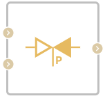
Block appearance in REPEAT VISION#
The Pilot-operated check valve (TL) block models a flow control valve in a thermal hydraulic network that provides variable flow direction depending on the pilot line pressure.
Description of valve operation
The unit has three thermohydraulic ports – A, B and X, the last of which is connected to the pilot line.
Fluid flow between port A and port B (forward direction) is always open.
Fluid flow between port B and port A (reverse direction) is either closed or open (partially or completely) depending on the position of the valve. The valve begins to open when the control pressure rises above the opening pressure setpoint. The valve is fully open when the control pressure reaches or exceeds the opening pressure setpoint.
Important
Fluid flow between port A and port X, and between port B and port X, is not possible.
Block properties
The Pilot pressure direction property can have the values Valve Opening and Valve Closing and determines the direction of action of the pilot pressure.
The Pilot configuration property allows the user to choose between a rigid or non-rigid connection between the pilot mechanism and the valve disc.
Note
For more details, see the Coil configuration section.
The Opening pilot pressure specification property determines the calculation method for the pilot pressure P\(_{pilot}\), either the differential pressure between ports X and A, or the excess pressure at port X.
Also, to configure the valve operation, the user sets two setpoints with which the current value of the control pressure P\(_{control}\) is compared:
differential for the start of valve opening (P\(_{cracking}\));
differential for full valve opening (P\(_{max}\)).
Pilot pressure P\(_{pilot}\) is the differential pressure of the control pilot, which depends on the value of the Opening pilot pressure specification block property and is:
pressure difference between port X and port A;
the difference between port X and atmospheric pressure, or, in other words, the excess pressure at port X.
Calculation of control pressure
When the Pilot pressure direction parameter is set to Valve Open, the pilot pressure is calculated as (1) :
where:
P\(_{pilot}\) — pilot pressure calculated above in the section Pilot pressure calculation;
K\(_p\) — the value of the parameter Port X to port A ratio area (2) :
\(P_A-P_B\) – measured pressure drop across the valve.
When the Pilot pressure direction parameter is set to Pilot to close, the control pressure is (3) :
If the Pilot pressure direction parameter is set to Pilot to open, the spool and disc can be configured as either rigidly coupled or decoupled. In the first case, the pilot pressure is determined only in accordance with the opening specification (the difference between ports X and A, or the excess pressure in port X); in the second case, if the pilot pressure is negative, it is re-measured as the difference between ports A and B, and the control pressure takes the value (4) :
When the Pilot pressure direction parameter is set to Pilot to close, the pilot spool and disc are always disconnected, and the pilot pressure can only be the differential pressure between ports X and A. In this case, if the pilot pressure is negative, it is also re-measured as the difference between ports A and B, and the control pressure takes the value (4).
Calculation of the valve cross-sectional area
The current value of the cross-sectional area of the valve A\(_{valve}\) is calculated as (5) :
where the maximum valve area A\(_{max}\) and leakage area A\(_{leak}\) are block properties, and the normalized pressure P\(_{norm}\) is calculated as (6) :
where the pressure setpoint for starting to open the valve (P\(_{cracking}\)) and the pressure setpoint for fully opening the valve (P\(_{max}\)) are block properties, and the control pressure is defined by the block as shown above in the relevant section.
Equation for mass flow rate
Law of conservation of mass (7):
Mass flow through valve (8):
where:
\(C_{d}\) – loss coefficient during pressure recovery;
\(A_{valve}\) - actual cross-sectional area of the valve, [m\(^2\)];
\(А_{port}\) - cross-sectional area of ports, [m\(^2\)];
\(\bar ho\) – average density of liquid (between the inlet and outlet ports), [kg/m\(^3\)];
\(\Delta p\) – pressure drop across the valve, [Pa].
Critical pressure drop \(\Delta p_{crit}\) - pressure drop associated with the critical Reynolds number, the transition point of the flow regime from laminar to turbulent (9):
Pressure loss describes the decrease in pressure in a valve when the cross-sectional area of the valve decreases.
\(PR_{loss}\) is calculated using the following formula (10):
Pressure recovery describes the positive change in pressure in a valve as the area increases.
Law of conservation of energy (11):
where:
\(\phi_A\) - energy flow at the input, [W];
\(\phi_B\) - energy flow at the output, [W].
1. Properties#
Property |
Default Value |
Description |
Units of measurement |
|---|---|---|---|
Pilot pressure direction: |
Pilot to open |
- |
- |
Pilot configuration: |
Connect spool and poppet |
- |
- |
Opening pilot pressure specification: |
Port X and port A pressure drop |
- |
- |
Cracking press drop |
10000.0 |
- |
Pa |
Maximum opening press drop |
20000.0 |
- |
Pa |
1.0 |
- |
- |
|
Maximum valve area |
1.0E-4 |
- |
m\(^2\) |
Leakage area |
1.0E-10 |
- |
m\(^2\) |
Port area |
0.1 |
- |
m\(^2\) |
Discharged coefficient, available when selecting |
0.64 |
- |
- |
Critical Reynolds number |
150.0 |
- |
- |
Smoothing factor |
0.01 |
- |
- |
Off |
- |
- |
2. Inputs and outputs#
Parameters |
Input/Output |
Description |
Units of measurement |
Port type |
|---|---|---|---|---|
Input |
Input |
- |
- |
Thermohydraulics |
Pilot line |
Input |
- |
- |
Thermohydraulics |
Output |
Output |
- |
- |
Thermohydraulics |
In order to see the connection capabilities of the block, you need to go to page Description of block ports