

Ball valve (TL)#
Block appearance in REPEAT VISION#
The Ball valve (TL) simulates the operation of this shutoff and control device in a thermal hydraulic system.
Note
The user has the ability to adjust the maximum area of liquid flow through the crane and the maximum throughput of the crane in dimensions:
The degree of valve opening in degrees is set through the external automation port.
Note
Zero signal means a fully closed valve.
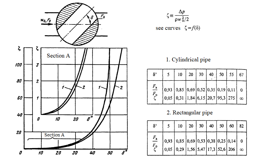
Calculation of the open area for liquid flow is made according to Idelchik handbook for cylindrical pipe according to the following figure :
Calculation of open area for liquid flow#
Note
Also, the user can select a table data setting by specifying a pair of vectors in three different ways:
Coefficient vector \(K_v\) and valve rotation angle vector
Coefficient vector \(C_v\) and valve rotation angle vector
Crane cross-sectional area vector and valve rotation angle vector
The block retains mass so that (3) :
This mass balance implies that the velocity increases as the area decreases and decreases when the flow discharges over a larger area. According to Bernoulli’s principle, this change in velocity results in a region of lower pressure in the hole and higher pressure in the expansion area. The resulting increase in pressure, called pressure recovery, depends on the pressure recovery loss ratio and the area ratio of the hole and port.
Mass flow rate calculation
The block calculates the mass flow rate (4) :
where:
\(C_d\) – coefficient of losses during pressure recovery;
\(A_{orifice}\) - hole area, [m\(^2\)];
\(A_{port}\) — cross-sectional area of ports A and B, [m\(^2\)];
\(\bar ρ\) – average liquid density, [kg/m\(^3\)].
Pressure loss
Pressure loss describes a decrease in valve pressure due to a decrease in area. Pressure loss, \(PR_{loss}\) calculated as (5) :
Critical pressure
Critical pressure drop, \(Δp_{crit}\) , is the pressure drop associated with the critical Reynolds number, \(Re_{crit}\), which is the transition point between laminar and turbulent liquid flow (6) :
Law of conservation of energy
where:
\(\phi_A\) - energy flow at the input, [W];
\(\phi_B\) - energy flow at the output, [W].
1. Properties#
Property |
Default Value |
Description |
Units of measurement |
|---|---|---|---|
Valve parametrization: |
Area |
- |
- |
Flow coefficient parametrization: |
\(K_v\) |
- |
- |
\(K_v\), when selecting |
49.0 |
- |
m\(^3\)/h |
\(C_v\), when selecting |
32.0 |
- |
gpm |
Discharge coefficient, when selecting |
0.64 |
- |
- |
Critical Reynolds number |
150.0 |
- |
- |
Leakage area, when selecting |
1.0E-10 |
- |
m\(^2\) |
Area port, when selecting |
0.09 |
- |
m\(^2\) |
Area ball bore, when selecting |
0.07 |
- |
m\(^2\) |
\(K_v\) vector, when selecting |
{1.0E-6; 0.34; 0.76; 1.6; 2.45; 4.1; 5.75; 9.4; 13.0; 28.0; 50.0} |
- |
- |
\(C_v\) vector, when selecting |
{1.0E-6; 0.58; 1.15; 1.9; 2.8; 4.3; 7.0; 10.5; 17.0; 26.0; 32.0} |
- |
- |
Area vector, when selecting |
{1.0E-10;62.5;125.0;187.5;250.0;312.5;375.0;437.0;500.0;562.5;625.0} |
- |
- |
Ball rotation vector, when selecting |
{0.0; 0.15707963267948966; 0.3141592653589793; 0.47123889803846897; 0.6283185307179586; 0.7853981633974483; 0.9424777960769379; 1.0995574287564276; 1.2566370614359172; 1.413716694115407; 1.5707963267948966} |
- |
- |
2. Inputs and outputs#
Parameters |
Input/Output |
Description |
Units of measurement |
Port type |
|---|---|---|---|---|
Opening angle |
Input |
- |
degrees |
Automation |
Input |
Input |
- |
- |
Thermohydraulics |
Output |
Output |
- |
- |
Thermohydraulics |
In order to see the connection capabilities of the block, you need to go to page Description of block ports