

IN Arduino PIN#
Block appearance in REPEAT VISION#
The IN Arduino PIN represents an input pin of the Arduino Nano, Uno, and Mega boards.
In the Signal name block property, the signal coming from the board to the REPEAT VISION model: Digital, Analog and NotRead. When selecting Digital or Analog signal, the block will check the value coming from the external device to the board control pin. When selecting NotRead signal, the block does not check the pin information, but only marks the selected pin as an input.
Depending on the selected signal, the PIN Number property must contain the pin number from which the information from the board to the model will be transmitted. The PIN Mode property is responsible for the INPUT and INPUT_PULLUP input pin modes, which differ in that the latter uses the board’s internal pull-up resistor to ensure signal stability. This is how the board’s input pin is initialized.
Important
Only the digit of the selected pin is written to the PIN Number property. The definition of an analog or digital pin is done via the Signal name property.
Pin numbers for Arduino boards:
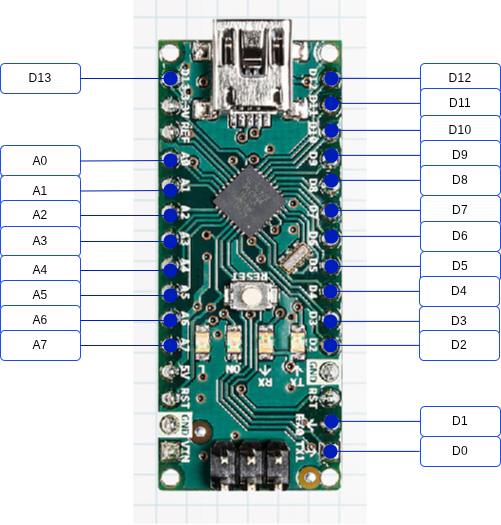
Fig. 1 Arduino Nano#
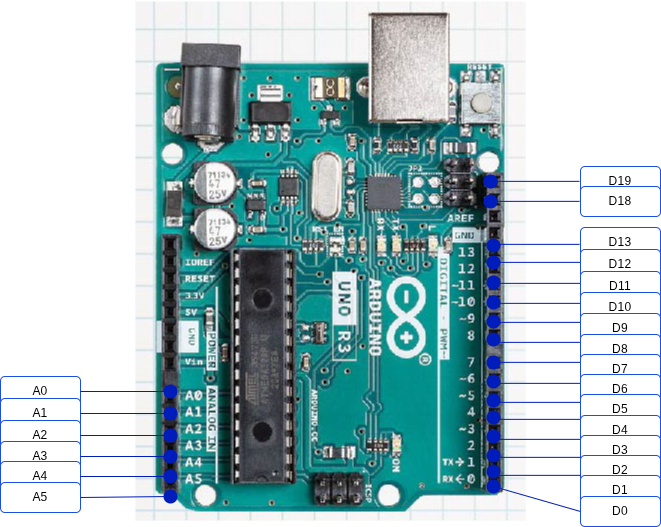
Fig. 2 Arduino Uno#
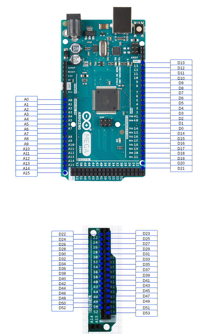
Fig. 3 Arduino Mega#
1. Properties#
Property |
Default Value |
Description |
Units of measurement |
|---|---|---|---|
Signal name: |
Digital |
Defining the input signal of the model |
- |
1 |
Input pin number of the control board |
- |
|
PIN Mode: |
INPUT |
Control board input pin mode |
- |
2. Inputs and outputs#
Parameters |
Input/Output |
Description |
Units of measurement |
Port type |
|---|---|---|---|---|
Output |
Output |
- |
- |
Automation |
In order to see the connection capabilities of the block, you need to go to page Description of block ports
3. Code generation#
Important
Block supports C source code generation