

Orifice (P)#
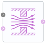
Block appearance in REPEAT VISION#
The Orifice (P) unit simulates flow through a local constraint with a constant or variable hole area. The opening area is parameterized either linearly or using a lookup table.
The unit retains mass so that (1):
This mass balance implies that the velocity increases when the area decreases and decreases when the flow is discharged over a larger area. In accordance with Bernoulli’s principle, this change in velocity results in a region of lower bore pressure and higher expansion are pressure. The resulting increase in pressure, which is called pressure recovery, depends on the loss coefficient at restoring pressure and the ratio of the areas of the hole and port.
Mass flow calculation
The unit calculates the mass flow rate as follows (2):
where:
\(C_d\) – discharge coefficient;
\(S_r\) – area of the hole, [m\(^2\)];
S — cross-sectional area of ports A and B, [m\(^2\)];
\( ho\) – gas density, [kg/m\(^3\)];
p - gas pressure, [Pa];
\(\gamma\) - adiabatic exponent.
Linearization of the equation for \(\frac{p_{out}}{p_{in}}\)>B\(_{lam}\) (3):
When the pressure ratio is less than the ratio \(\frac{p_{out}}{p_{in}}\) < \((\frac{2}{\gamma +1})^\frac {\gamma}{\gamma-1}\) the equation assumes (4):
Energy conservation law (5):
where:
\(\phi_А\) - energy flow at the input, [W];
\(\phi_В\) - energy flow at the output, [W].
1. Properties#
Property |
Default Value |
Description |
Units of measurement |
|---|---|---|---|
Orifice type: |
Variable |
- |
- |
Port area |
0.001 |
- |
m\(^2\) |
Orifice area |
1.0E-4 |
- |
m\(^2\) |
Orifice area vector |
{1.0E-9; 2.0352E-7; 4.0736E-5; 1.1438E-4; 3.4356E-4;} |
- |
m\(^2\) |
Discharge coefficient |
0.64 |
- |
- |
Laminar flow pressure ratio |
0.999 |
- |
- |
2. Inputs and outputs#
Parameters |
Input/Output |
Description |
Units of measurement |
Port type |
|---|---|---|---|---|
Auto, available when |
Input |
- |
- |
Automation |
Input |
Input |
- |
- |
Pneumatics |
Output |
Output |
- |
- |
Pneumatics |
In order to see the connection capabilities of the block, you need to go to page Description of block ports
3. Examples of use#
Examples of using this block can be found in the following sections:
Description of Demo.
Tutorials
Library |
Tutorial name |
|---|---|
|
How-to guides
Section |
Guide name |
|---|---|
Machine learning approximation |
|
Solving optimization tasks |
Maximizing gas production rate in the gas well cluster collection system |