

Creating a battery management system#
This section provides an overview of the Battery Management Control system (BMS) model. BMS model is developed on the REPEAT VISION platform.
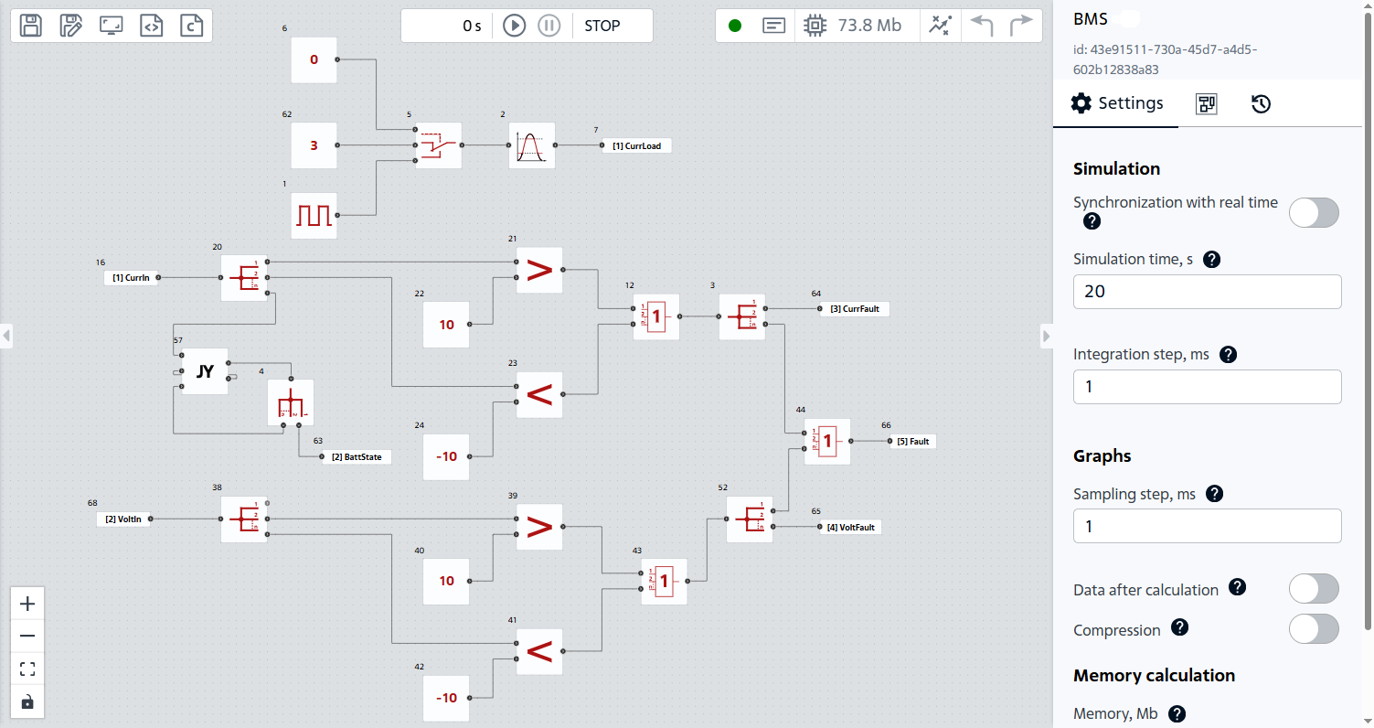
BMS model#
In this section, you will learn:
What is BMS;
Main functions of BMS;
Which manufacturers use BMS;
Example of BMS model executed in REPEAT VISION;
Example of a battery model with BMS;
Example of BMS with active cell balancing;
Why model-oriented approach in BMS development is important.
1. What is BMS#
The performance of lithium-ion batteries is significantly dependent on temperature, so it is important to operate the SB within acceptable thermal limits.
A BMS is a device designed to monitor charging and discharging of storage battery. Main BMS function is to ensure the safe operation of the battery by monitoring its state, which maximizes SB life. Below there is a simplified block diagram of an electric vehicle with BMS, which monitors the parameters of traction accumulator and depending on its state generates control signals for optimal operation conditions.
Блок-схема упрощенного электромобиля/Block diagram of a simplified electric vehicle
2. What are the main functions of BMS#
BMS performs a number of functions that contribute to improving the safety quality of SB operation:
Communication with other system components (information transfer);
2.1. Monitoring of basic parameters#
The system measures the following parameters:
Voltage;
Current;
Temperature;
State-of-Charge (SOC);
Operating mode: charge, discharge, idling run (idle).
2.2. Cell balancing#
Cell balancing is the process of equalizing the voltages and charge levels of cells. Balancing is achieved by preventing undercharging/overcharging of individual SB cells, for example, the redistribution of energy from the most charged cells to the least charged, which is called the active balancing method. Passive balancing uses shunt resistors to dissipate electricity.
2.3. Recuperation#
Electric vehicle recuperation is the process of converting kinetic energy into electric energy and then returning it to the battery pack. Recuperation is achieved by quickly determining the mode of operation of the battery and conducting appropriate switching operations in the circuit.
2.4. Communication with other system components#
The data generated by the BMS is also transmitted to other parts of the system where the battery is installed (see diagram above).
2.5. Protection against abnormal operation#
In order to prevent failures, the SB is protected against the following operation modes:
Overvoltage/undervoltage;
Overcurrent/overcurrent;
Supercooling/overheating.
3. Where is this technology used#
This technology is critical for all manufacturers of devices in which the SB is installed, because with the help of this control system, manufacturers achieve increased reliability by ensuring operation safety, performance and economic efficiency. BMS are used, for example, in Tesla S and Nissan Leaf.
4. Development of BMS in REPEAT VISION#
The initial BMS version will comprise algorithms to determine:
Abnormal operation modes;
Battery mode;
The charge level drops below the critical level;
SB temperatures, relative to chemical losses.
We will also introduce an embedded load into the BMS model to conduct test calculations of the model.
Most of the functions are implemented using automation units (load, determination of abnormal operation mode and charge level drop below critical).
When implementing the load, we’ll set block №5 Switch, blocks №6 and №62 Constant, block №1 Rectangular pulse generator, and block №2 Limiter. When performing calculations, you can select the load current value, the load type (pulse or constant) and the permissible current limit.
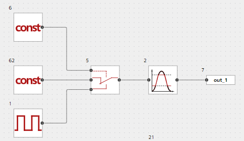
Load model#
The simplest part of the development will be the algorithm for determining abnormal operating modes SB: blocks №21,23,39,41 comparisons (Greater, Less) with acceptable values and blocks №12,43,44 Logical OR. If any of the emergency modes occurs, the output of BMS will be 1.
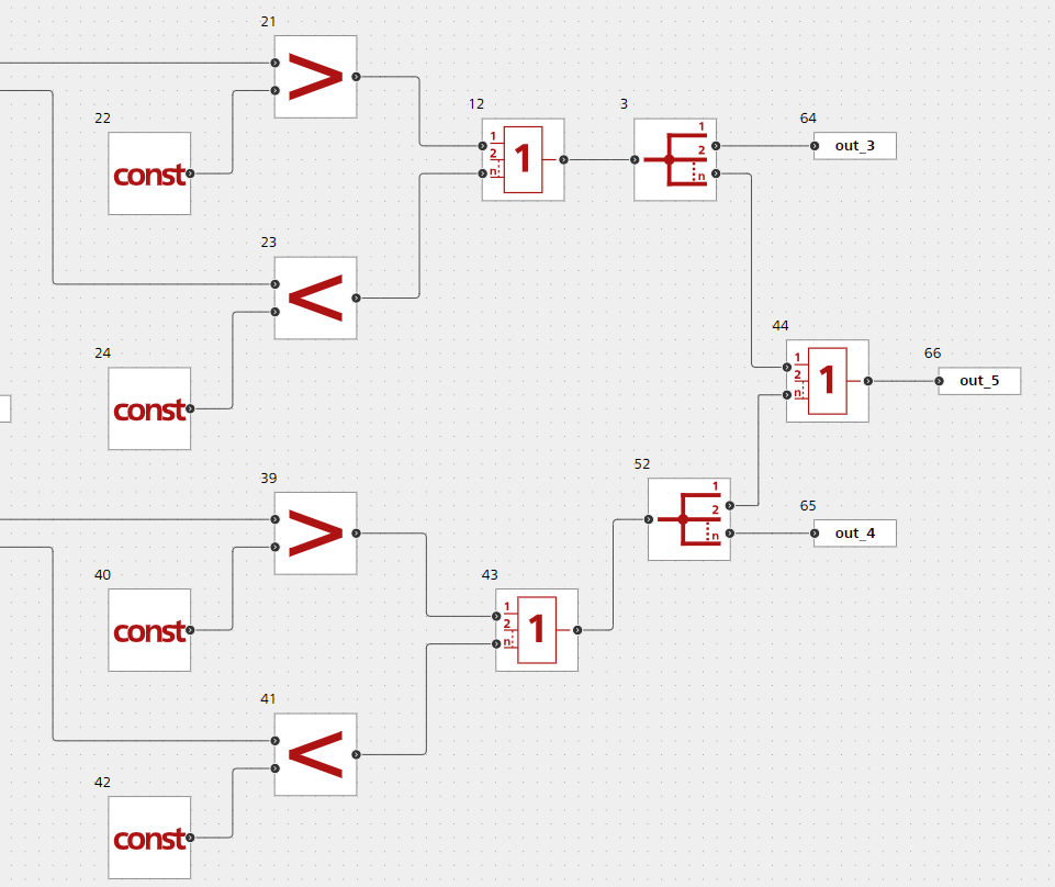
Determination of abnormal operation mode#
Now let’s move on to a more interesting part: the implementation of the algorithm for determining the battery operating mode, for this we implement the simplest state machine, i.e. a model in which the subsequent state of the model depends not only on the input signal, but also on the state at the moment.
There are a number of ways to implement this algorithm, we will write a script using the Jython block, in which the Python language is integrated into the Java ecosystem.
Below is a visual representation of the structure of the machine being developed. In addition to the transition between three states (charge, discharge, idle run), it is also necessary to implement a time condition, since the system checks the state at a certain interval, for example:
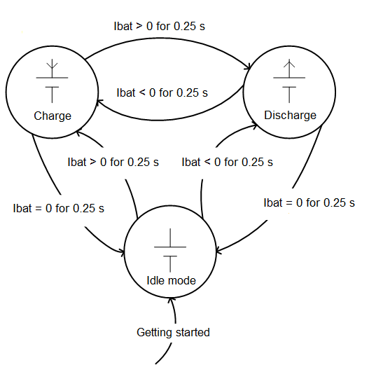
State machine graph#
At the beginning of the script, we initialize the class with three states:
class State: #Класс состояний АКБ
    Idle = 0.0 #Холостой ход
    Discharge = 1.0 #Разряд
    Charge = 2.0 #Заряд
Before writing the script, it is worth noting that the BMS test will be carried out in an electric circuit with imperfect sources, so the current in a closed circuit cannot be equal to 0. We will set the condition that the idle mode will correspond to:
interval -1е\(^{-6}\)≤ \(I_{АКБ}\)≤1е\(^{-6}\), discharge \(I_{АКБ} >1е\)^{-6}\(, __charge__ \)I_{АКБ}\(<-1е\)^{-6}$
def CheckState(Ibatt): #Функция по определению состояния относительно тока Ibat
    global state #Переменная состояния
    global time #Переменная времени
    incrTime(in_2 ) #Функция для реализации счетчика времени
    if time < 0.25:
        if in_3 == 0:
            state = State.Idle
        elif in_3 == 1:
            state = State.Discharge
        elif in_3 == 2:
            state = State.Charge
        return state
    else:
        if state == State.Idle:
            if Ibatt <= 1e-6 and Ibatt >= -1e-6:
                state  = State.Idle
            elif Ibatt > 1e-6:
                state = State.Discharge
            elif Ibatt < -1e-6:
                state = State.Charge
        elif state == State.Discharge:
            if Ibatt > 1e-6:
                state  = State.Discharge
            elif Ibatt <= 1e-6 and Ibatt >= -1e-6:
                state = State.Idle
            elif Ibatt < -1e-6:
                state = State.Charge
        elif state == State.Charge:
            if Ibatt < -1e-6:
                state = State.Charge
            elif Ibatt <= 1e-6 and Ibatt >= -1e-6:
               state = State.Idle
            elif Ibatt > 1e-6:
                state = State.Discharge
        time = 0.0
        return state

out_1 = CheckState(in_1) #Первый выходной порт состояния АКБ
out_2 = ShowTime() #Второй выходной порт счетчика
Script for state machine implementation (In case of charging, the output value = 2, when uncharging = 1, at idle = 0)
Let’s check the operability of the developed script, apply step current to the input, corresponding to idle run, discharge and charge:
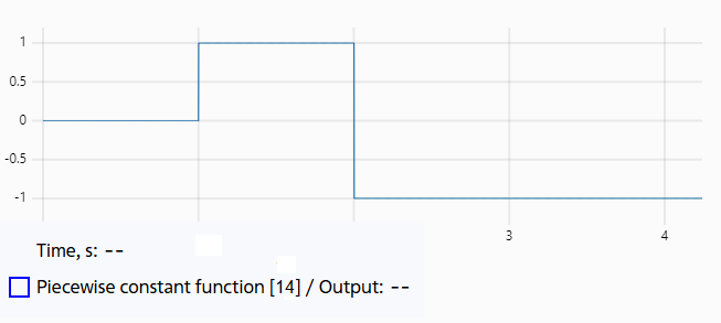
Step current#
According to results, the state machine correctly shows the state of the system relative to the current with the required time interval.
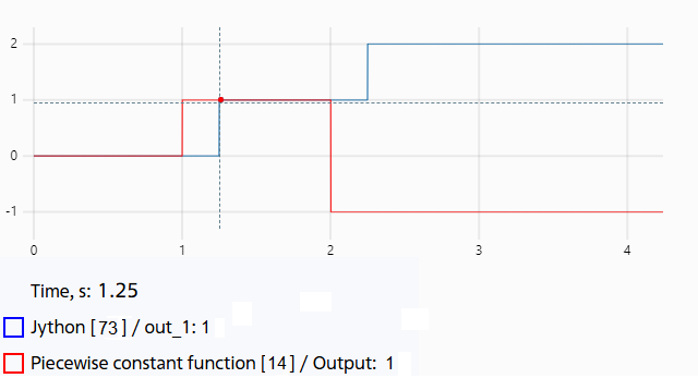
Jython test results#
Thermal model is represented by one Thermal mass (block №10), reflecting the properties of the SB electrodes. Temperature change is determined by chemical losses (block №8) and cooling efficiency of ambient air (block №71 and block №13).
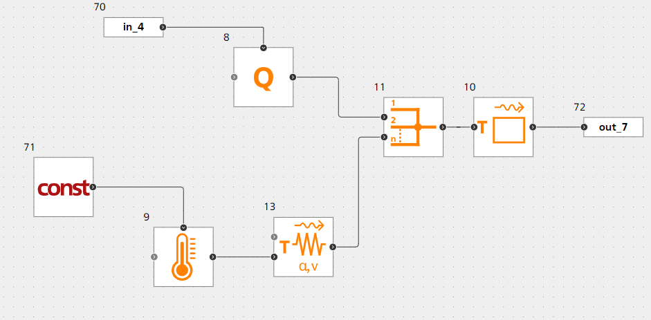
SB temperature determination model#
5. Development of battery model with BMS#
Before starting the calculations, we will once again designate BMS output signals (sequentially from top to bottom):
Load current;
SB operation mode (State);
Abnormal current operation mode (CurrentFault);
Abnormal voltage operation mode (VoltageFault);
Abnormal operation mode (Fault);
Lower charge level (SOCdrop);
SB temperature (TempOut).
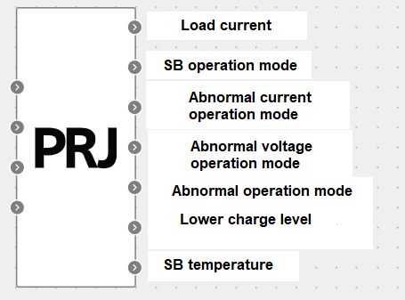
BMS output signals#
Let’s study the operating principle of the BMS in the model, consisting of a Battery (block №2) and a Current source (block №3), to the command port of which the value of the load current signal is fed:
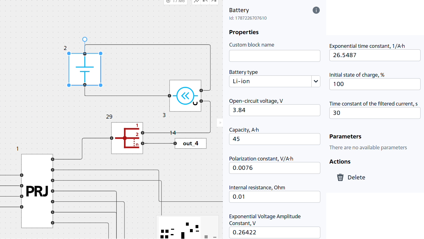
Test diagram of the model#
Connect the current, voltage, charge level (SOC) and total heat loss power sensors of the SB to the BMS input ports.
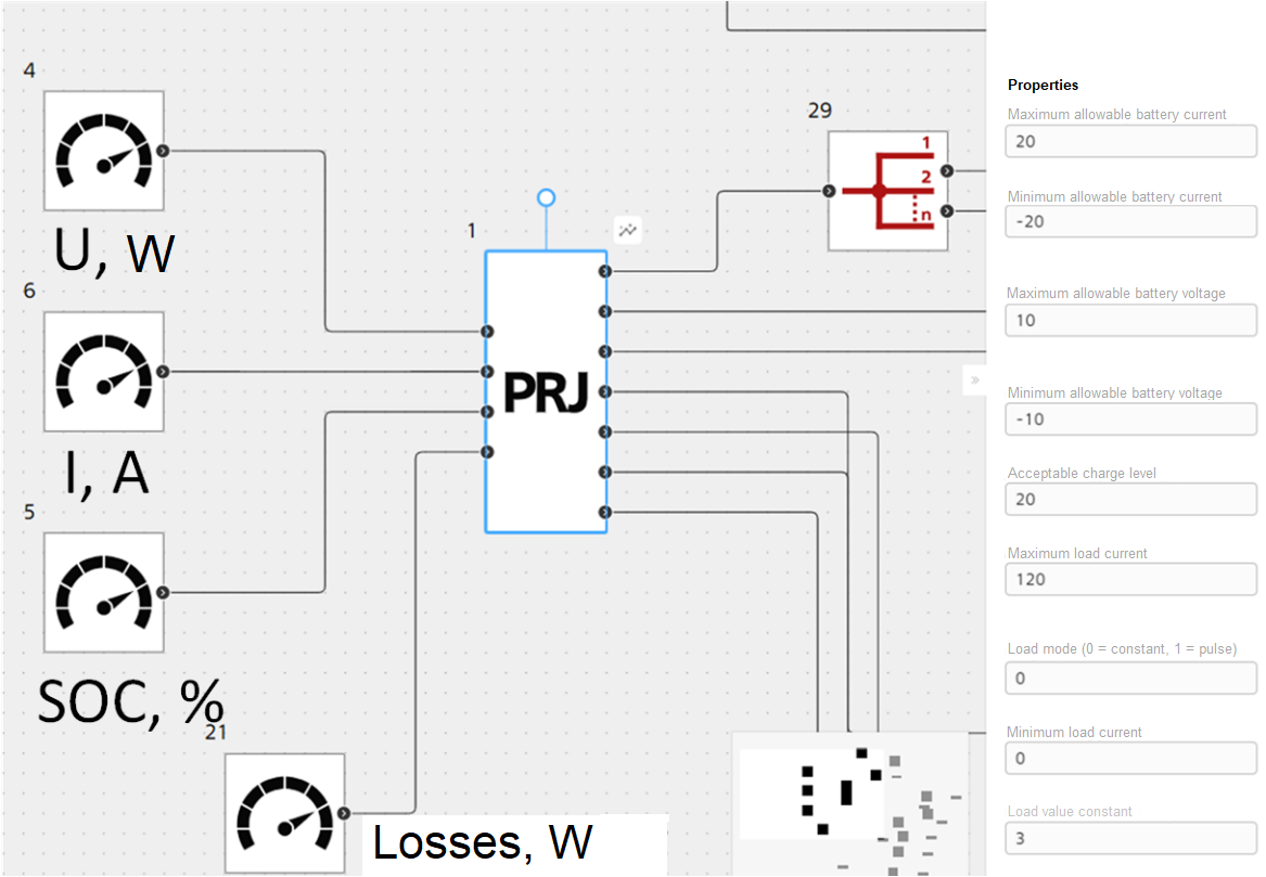
BMS input signals#
Next, we will establish a connection between the developed model and the built-in JupyterLite tool, a detailed tutorial on this process is presented in the video.
In order to study the dependence of the SB temperature on the load current, let’s start a series of calculations with an increasing load current from 0 to 120 [A].
LoadCurrent |
|
|---|---|
0 |
0.0 |
1 |
30.0 |
2 |
60.0 |
3 |
90.0 |
4 |
120.0 |
Input data for SB calculation series with BMS
Temperature curves are shown below.
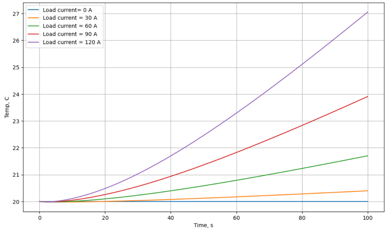
Temperature curves at different load currents#
The comparison characteristic shows how the temperature changes significantly with increasing load current, which allows us, at a known value of the permissible SB temperature, to set the maximum operating current.
We will carry out another single calculation at a load current of 5 [A] and display a table of values of monitored parameters (right-to-left: load current, SB state, abnormal current mode, abnormal voltage mode, charge level, SB temperature).
BatteryCurrent |
State |
CurrentFault |
VoltageFault |
BatterySOC |
TempOut |
|---|---|---|---|---|---|
0.00 |
0.00 |
0.00 |
0.00 |
0.00 |
20.00 |
5.00 |
1.00 |
0.00 |
0.00 |
100.00 |
20.00 |
5.00 |
1.00 |
0.00 |
0.00 |
100.00 |
20.00 |
5.00 |
1.00 |
0.00 |
0.00 |
100.00 |
20.00 |
5.00 |
1.00 |
0.00 |
0.00 |
100.00 |
20.00 |
5.00 |
1.00 |
0.00 |
0.00 |
100.00 |
20.00 |
5.00 |
1.00 |
0.00 |
0.00 |
100.00 |
20.00 |
5.00 |
1.00 |
0.00 |
0.00 |
100.00 |
20.00 |
5.00 |
1.00 |
0.00 |
0.00 |
100.00 |
20.00 |
5.00 |
1.00 |
0.00 |
0.00 |
99.99 |
20.00 |
5.00 |
1.00 |
0.00 |
0.00 |
99.99 |
20.00 |
5.00 |
1.00 |
0.00 |
0.00 |
99.99 |
20.00 |
5.00 |
1.00 |
0.00 |
0.00 |
99.99 |
20.00 |
5.00 |
1.00 |
0.00 |
0.00 |
99.99 |
20.00 |
5.00 |
1.00 |
0.00 |
0.00 |
99.99 |
20.00 |
5.00 |
1.00 |
0.00 |
0.00 |
99.99 |
20.00 |
5.00 |
1.00 |
0.00 |
0.00 |
99.99 |
20.00 |
5.00 |
1.00 |
0.00 |
0.00 |
99.99 |
20.00 |
5.00 |
1.00 |
0.00 |
0.00 |
99.99 |
20.00 |
Calculation results table
Since there are zeros in the columns for determining abnormal modes by current, voltage (VoltageFault and BatterySOC). SB operates within permissible limits.
However, we considered the SB operation with a static load. What if the battery powers a dynamic load, for example, Electric drive (ED) of an electric vehicle ?
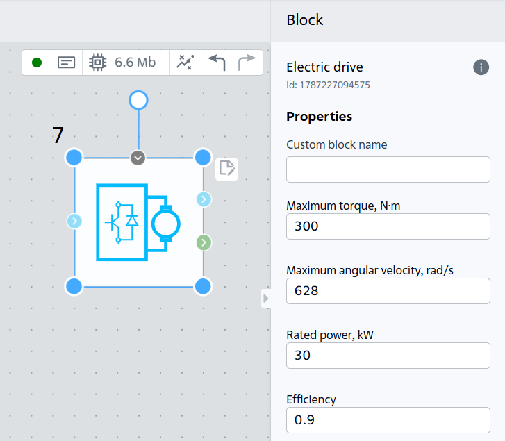
Electric drive block#
Let’s update model and parameters BMS.
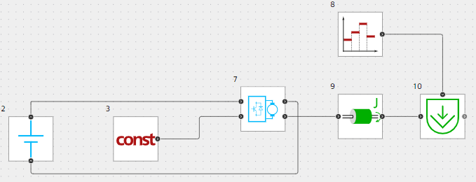
SB and ED model#
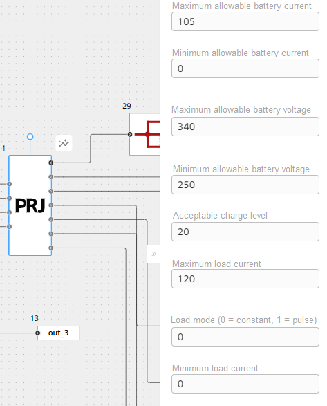
Updated BMS parameters#
ED torque characteristics is given below, where the blue line is the characteristics of the load and the red line is the torque of the electric drive.
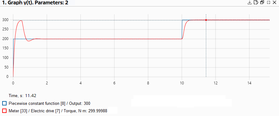
Torque characteristics of ED#
According to the obtained results, current exceeds the permissible values during start-up, when it goes into generator mode, and also when it reaches the maximum torque (300 [N \( \cdot \) m]).
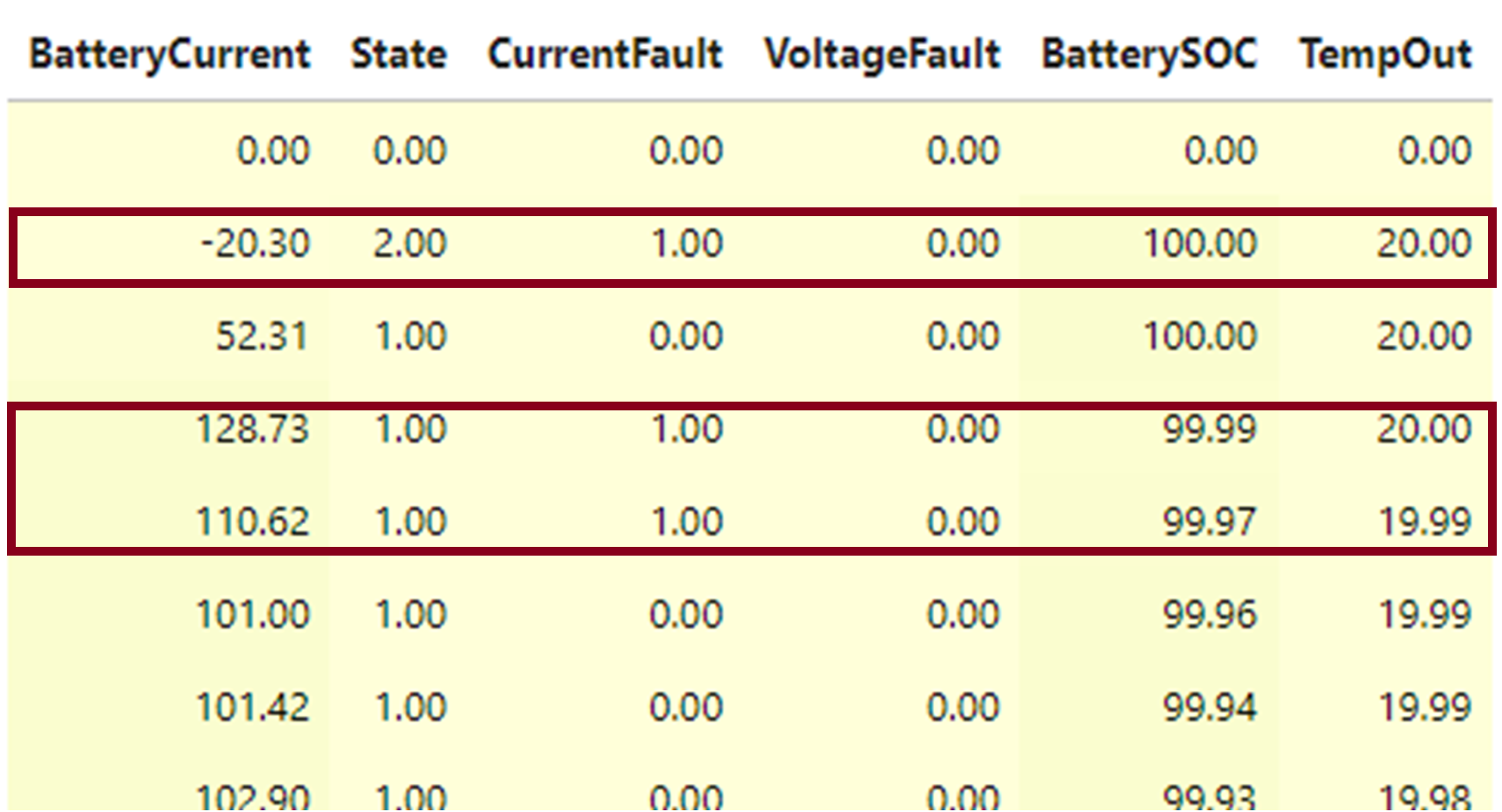
Calculation results table#
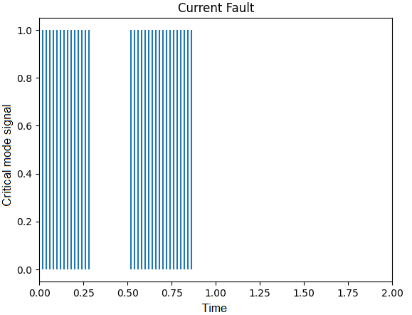
Diagram of abnormal modes by current#
These results show that the SB does not operate within the permissible ranges, since the maximum battery current is exceeded and it is required to ensure the safety of the SB operation when powering the ED, which can be achieved in different ways: from reducing the ED load to developing a controlled traction converter.
6. Development of BMS with active cell balancing#
Since the active balancing of the cells of the battery pack is one of the main functions of the BMS, the BMS model is supplemented with an appropriate algorithm. Active balancing methods comprise:
Based on capacitor components;
Based on inductive components;
Based on transducers.
Consider balancing based on a single inductor that transfers energy between batteries.
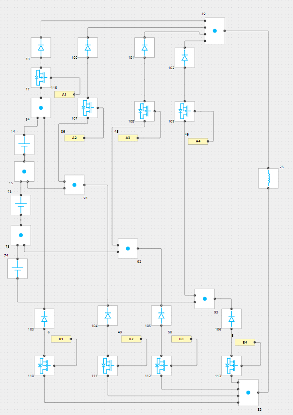
Model of three battery cells with active balancing#
Due to the large scope of this article, a full review of the model with active balancing will be done in the next chapter. At the moment, let’s present the calculation results in a model in which at the initial moment of time the cells have different charge levels (60.01, 60.03, 60.05 % respectively).
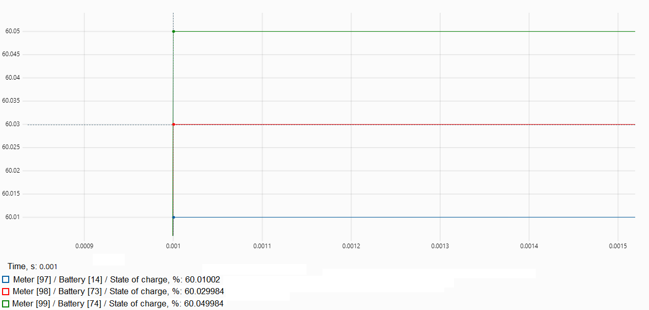
Battery charge levels before balancing (blocks №14,73,74)#
Since the difference in charges is insignificant, the BMS equates them charge levels in 0.5 seconds
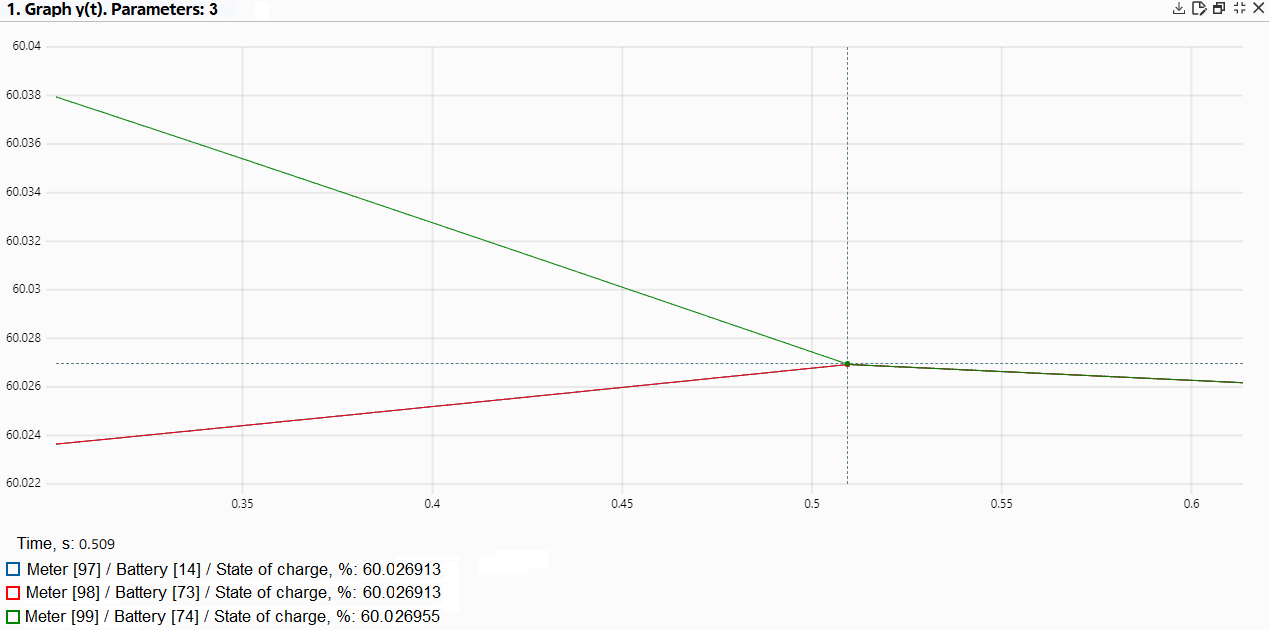
Battery levels after balancing#
7. Why model-oriented approach in BMS development is important#
With model-oriented design, it becomes possible to study the developed system under various conditions from operating to emergency modes, optimize its parameters and conduct a series of tests before switching to prototype development - all this significantly increases the economic efficiency of the development process.