

Traffic light on ARDUINO#
The guide considers the implementation of a traffic light model using library blocks Automation of the REPEAT VISION platform. It describes the process of source C-code generation (see description code generation) of the model and its transfer to the physical board Arduino UNO.
Let’s consider the main design stages:
Hint
Model creation simplifies the development of the traffic light operation algorithm.
Let’s consider the task of traffic light control on the Arduino UNO board based on ATmega328H-AU microcontroller. It is known that one traffic light cycle (see Fig. 1 below) represents the following sequence:
red color is glowing for 10 seconds;
yellow color lights up in the last 3 seconds;
then green color turns on and operates for 10 seconds;
then green color blinks once in 5 seconds;
yellow color turns on for 3 seconds;
cycle gets completed.
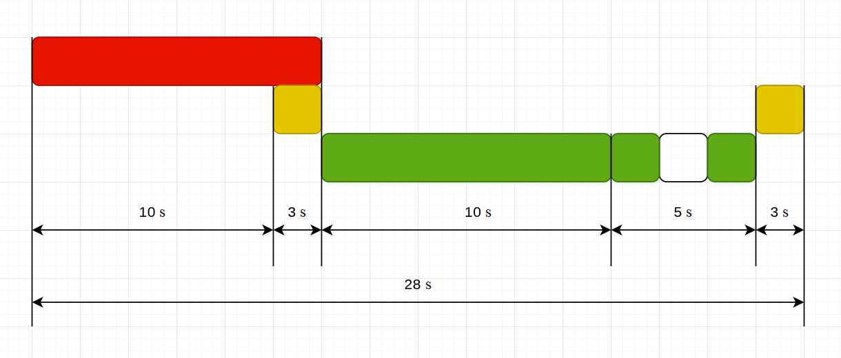
Fig. 1 Temporary diagram of traffic light operation#
Hint
It is proposed to
Download the model file to go from the theory to practice
1. Model creation#
Let’s select the Sawtooth wave block from the library (see Fig. 2 below). It will be needed to clearly demonstrate the actuation of each traffic light cycle. The total cycle duration is 28 [s] so let’s indicate that the period is equal to 28 [s], the height is 28 pitches in the block properties and set the phase and the minimum value of the peel equal to zero.
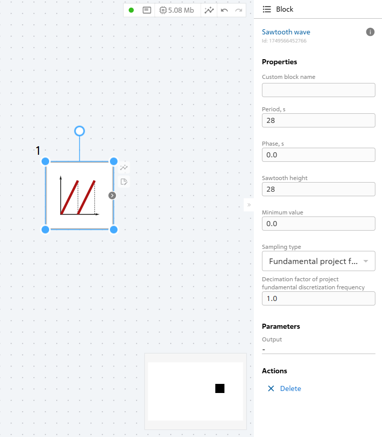
Fig. 2 Block Sawtooth wave#
Let’s divide one cycle of the program into three phases, first - ref traffic light operation, second - yellow LED operation, third - green LED operation. Let’s line up the logic of each cycle phase.
1.1. First phase - red LED#
The red LED operation logic is limited by a condition that it should not glow for more than 10 [s]. Let’s use blocks Less or equal and Constant (see Fig. 3 below). The control signal is transmitted form the block Sawtooth wave, and in Constant let’s set the value 10, then at the comparing block output we obtain a signal that operates in the range of values 0 to 10 inclusive.
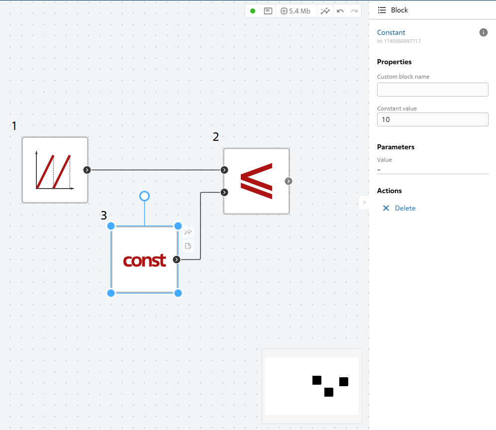
Fig. 3 First phase of the traffic light cycle#
1.2. Second phase - yellow LED#
The second phase describes the yellow LED operation (see Fig. 4 below). As you can see from the time chart, the yellow color occurs twice in one cycle and it also turns on for 3 [s] at the end of the red LED operation. As in the first phase, the control signal is transmitted from the block Sawtooth wave. Let’s consider in detail the process of yellow signal activation. It turns on at the 7th second from the cycle start, operates for 3 [s], turns off at 15 [s], then turns on again for 3 [s]. Due to the fact that the model logic will consist of blocks Constant, More or equal, Less or equal, Logical AND, Logical OR, Branching and will be divided into two check conditions.
The first condition is generated for the first 3 [s]. Let’s set value 7 to the one Constant, the moment of time at which the yellow light is activated, let’s connect it with the block More or equal and through Branching box let’s transmit the values Sawtooth wave to the same block. Then transmit connection from the Branching box to the block Less or equal, let’s transmit the value Constants 10 to the second output. Let’s transmit the outputs from the comparing blocks to the block Logical AND, there will be logic 1 at the block output only when both output signals reach the necessary temporary values.
The second condition starts the yellow LED for 3 [s] at the cycle end. The principle of construction is the same, as for the first one, but the one Constant is assigned the value 25 and the other 28. Let’s unite both conditions through the block Logical OR, which actuates only to the one of the signals.
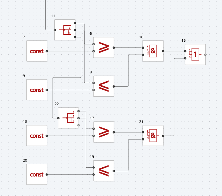
Fig. 4 Second phase of the svetofor cycle#
Important
When creating custom blocks (see fig. 5 below), blocks GO TO and GO FROM cannot be used in them as they do not register the external impact on the block.
Fig. 5 The “YELLOW LED” custom block#
The example of filling the custom block “YELLOW LED” Fig. 6:
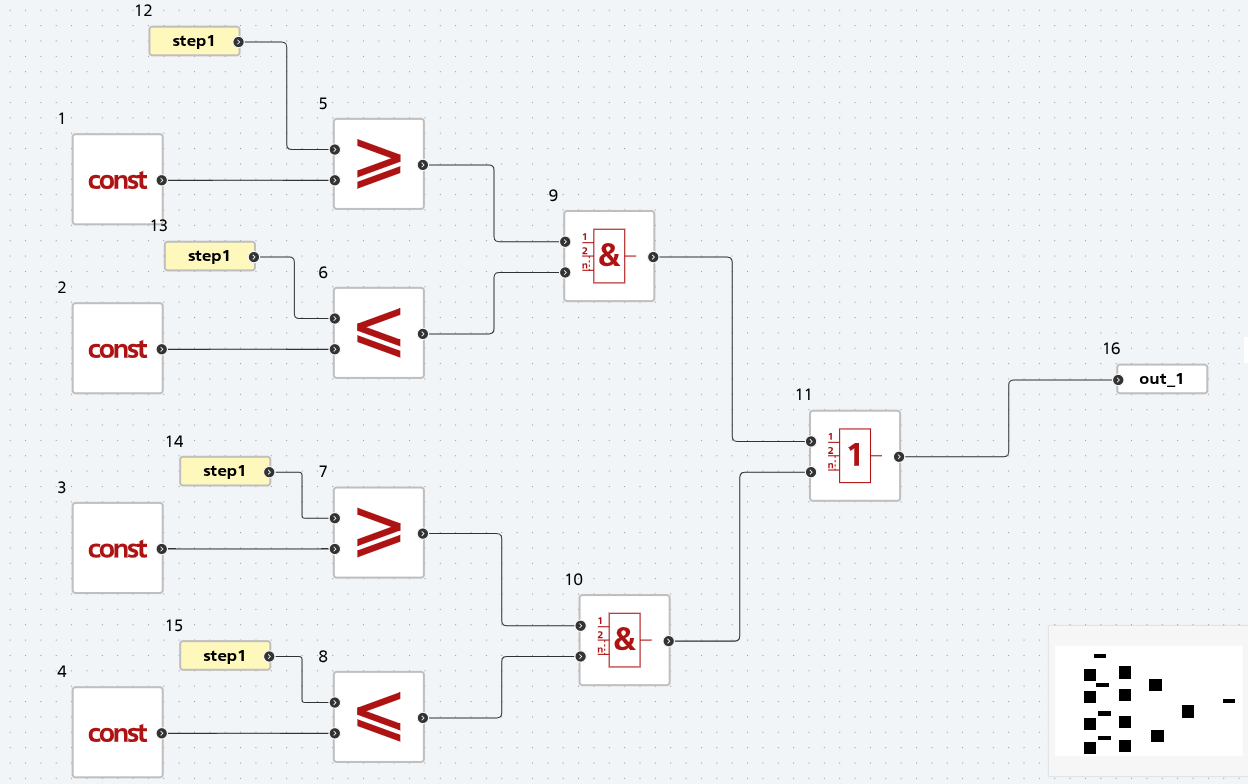
Fig. 6 The internal structure of the custom block#
1.3. Third phase - green LED#
Third phase – 10 [s] of uninterrupted green LED operation and 5 [s] per one blink (see Fig. 7 below). The green LED turns on at the 10th second of the whole cycle operation, at the 20th second it attenuates and performs one blink within 5 [s]. The state can also be divided into two conditions. In the first condition, let’s build a similar logic to the condition of the second phase, when the time interval from the 10th to the 25th second is set. The second condition turns off the LED at the 20th second and starts a single blink using the block Rectangular pulse generator, block values: а = 2000 [ms], b = 1000 [ms], с = 1, d = 0 [ms]. Both conditions are controlled through the block Switch, which serves as switch function .
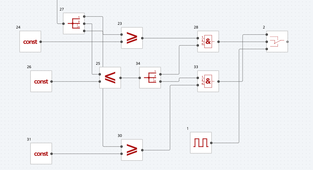
Fig. 7 Third phase of the traffic light cycle#
1.4. Model startup and check#
Let’s set the simulation time of the system to 100 [s], let’s remove the settings of synchronization with real time to increase the speed of operation. Let’s set the integration step and sampling rate to 1000 [ms] each. Let’s check the assembled model, for this purpose let’s start it and display the charts of the block Sawtooth wave (see Fig. 8 below) and three blocks completing each phase of LEDs:
red LED - block Less or equal (see Fig. 9 below);
ellow LED - blockLogical OR (see Fig. 10below);
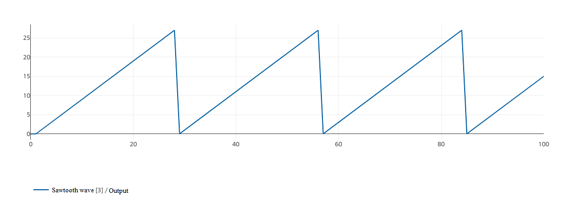
Fig. 8 Signal from block Sawtooth wave#
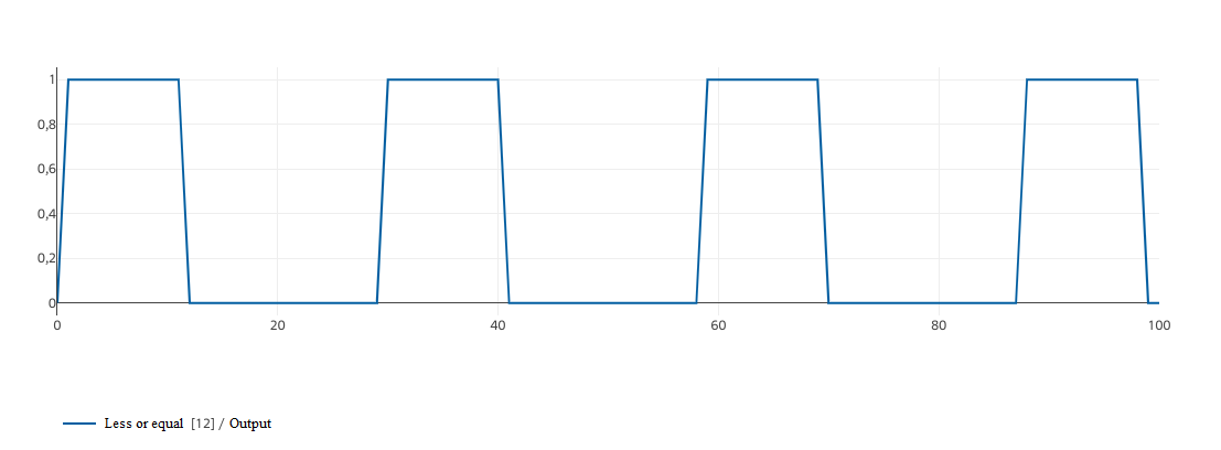
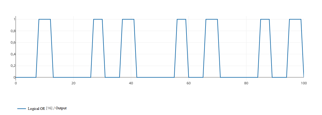
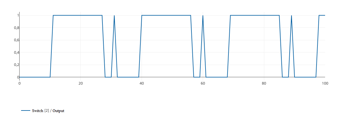
Fig. 11 Signal for green LED#
2. Creating model C-code sources in REPEAT VISION#
The REPEAT VISION has the ability to automatically generate C source code (see description code generation) for the assembled model, this function is implemented using the Generate C sources button (see. Fig. 12 below).
Set the blocks USDS output port to the output of each state, assign them the respective names RED, YELLOW, GREEN.
Note
Let’s record the values of LED control signals to this data.
Blocks USDS input port and USDS output port are required to create variables that will be input/output variables in the generated sources. The name specified in the properties of these blocks will then be used in the sources, which simplifies their integration into a user project.
Note
In this example, the output contacts simulate connections to the control board pins.
When the source code is successfully generated, an archive is created containing the following files:
The file with the extension
.ccontains a function, which describes the operation of the model for one calculation pitch, and all the necessary variables;The header file with the extension
.hdeclares all necessary variables and libraries for calculation of .

Fig. 12 Button Generate C sources#
3. Arduino project creation#
In the Arduino IDE environment, let’s create a new sketch named «sketch_svetofor.ino», then add the generated files from REPEAT VISION to it in the folder. They will be automatically opened in the environment. From the file with the extension .с let’s take the #include."svetofor.h" line, it acts as a library that describes the behavior of the model in the C language.
In the
void setup()function, let’s define the output pins for each LED:
#include "svetofor.h"
void setup() {
// put your setup code here, to run once:
pinMode(2,OUTPUT); // GreenOUT
pinMode(3,OUTPUT); // YellowOUT
pinMode(4,OUTPUT); // RedOUT
}
In the
void loop()function, let’s compose the main body of the program, where thesvetofor()function is taken from the source with the extension.c:
void loop() {
// put your main code here, to run repeatedly:
svetofor();
digitalWrite(2,GREEN>0&&(RED==0)&&(YELLOW==0));
digitalWrite(3,YELLOW>0);
digitalWrite(4,RED>0);
delay(controldtt*1000); // задержка по времени на 1000 миллисекунд = 1 секунда
}
The controldtt variable is the pitch calculation time and defaults to 1. The sketch is checked using the Verify button, as a result, a message is output that it has been checked and is using a certain amount of device memory.
4. Lining up the circuit on Arduino UNO#
In order to create a physical diagram (see Fig. 13 below), one needs:
three LEDs;
three 220 [kOhm] pull-up resistors;
5 connecting wires of «father-father» type;
arduino UNO;
USB cable «A-B».
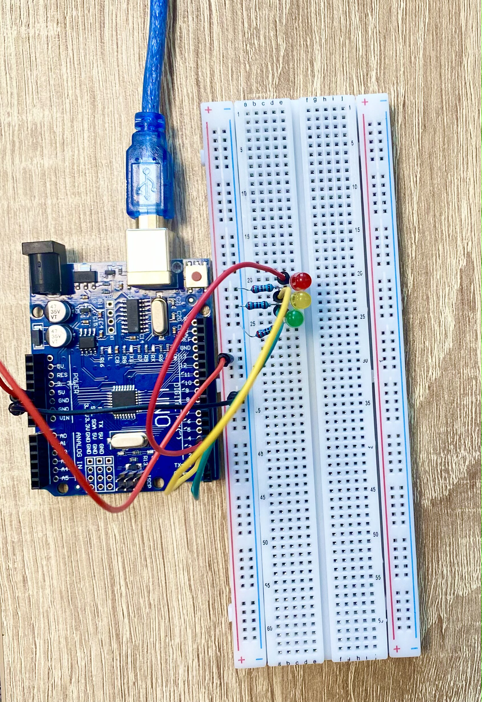
Fig. 13 Traffic light diagram on Arduino UNO#
5. Verification of results#
Let’s connect the physical system to the computer and start the sketch compilation. As a result, the traffic light sequence is worked out (see Fig. 14 below).

Fig. 14 Traffic light simulation#
6. Conclusions#
Based on the work performed:
Traffic light operation process on REPEAT VISION platform was implemented;
The capabilities of the application for automated generation of C sources were considered;
Thanks to these abilities REPEAT VISION, it was possible to assemble a physical traffic light model based on the Arduino UNO and put it into operation at the expense of the project sources.