

Home heating control system with Modbus TCP#
This practical guide demonstrates conducting a semi-naturalistic simulation in REPEAT VISION using the Modbus TCP protocol. The external physical device is an Arduino UNO controller paired with an ENC28J60 Ethernet module, and the simulated system is a thermal model of a house.
Semi-naturalistic modeling is a study in which part of a system’s mathematical model is a real physical object. Semi-naturalistic modeling methods are effectively used in the development and debugging of various automatic control systems.
Modern residential heating control systems require flexibility, scalability, and the ability to integrate with other “smart home” components. One of the most common protocols for industrial automation is Modbus, thanks to its openness and support by a wide range of devices. In particular, Modbus TCP is an Ethernet version of the protocol that provides convenient network interaction between controllers and field devices.
As an example of such a system, let’s consider a simple home heating control system controlled via Modbus TCP.
Important
Some of the blocks for this example, namely Modbus Client Settings, Modbus Write, Modbus Read, are only available for use in the local version of REPEAT VISION.
1. General structure of the model#
Thermal model of a house in REPEAT VISION (mat. model);
The control system is an Arduino UNO microcontroller in conjunction with an ENC28J60 Ethernet module, implementing the Modbus TCP server logic.
2. Thermal model of the house#
A thermal model is a dynamic model of the facility being developed, taking into account the required effects and operating conditions. Depending on the specific objectives and technical specifications, the model can be created with varying levels of detail to account for the physical processes occurring within the facility and its surrounding environment. Using a thermal model, you can calculate and optimize your heating system. It allows you to verify adopted technical solutions and mitigate risks before implementing the project as a real-life facility.
The thermal model, presented in Fig. 1, consists of the blocks of the libraries Automation and Heat exchange. The house’s main structures are composed of three thermal masses. The central thermal mass reflects the average parameters of the chosen structure, while the other two reflect surface temperatures.
The heater switches on and off when the air temperature in the house reaches 18 to 22°C. The air temperature at the heater outlet is 50°C. We will use these parameters as a guide when building the thermal model control system.
You can learn more about this model on the ROSATOM page.
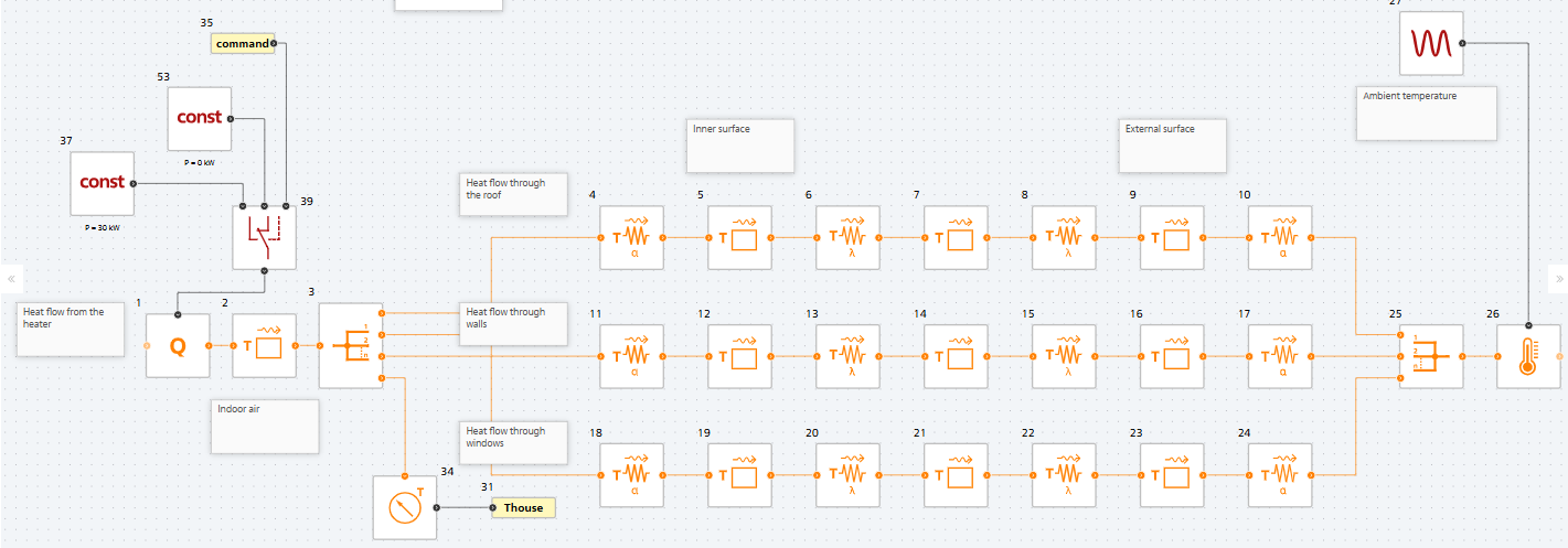
Fig. 1 Thermal model of the house#
3. Installing Modbus blocks in REPEAT VISION#
In the context of home heating control, the use of the Modbus TCP protocol allows for data exchange between the controller and the monitoring simulation model. Configuring the home heating model for communication via Modbus TCP is accomplished using Modbus blocks, which are located in the External models REPEAT VISION library. Three blocks are provided for working with Modbus TCP, which are shown in Fig. 2:
Modbus Client Settings – the block configures communication with the connected Slave device, namely such characteristics as IP address, port, connection time.
Modbus Write – the block writes values from the model to the registers of the external control controller.
Modbus Read – allows you to read values from an external controller and pass them to the model.
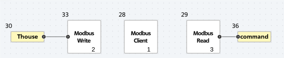
Since in this example we regulate the heater operation depending on the room temperature, we implement the following signal transmission logic. The temperature measurement is recorded by block №34 Temperature sensor, the signal from the block is transmitted to block №33 Modbus Write, which writes the signal value to the specified storage register. In the external controller, the temperature from the model is processed according to the condition that the incoming value ‘x’ must be between 18 and 22°C (1):
If the temperature value is within the set limits or less than 18 ℃, the controller transmits a switch-on signal, conditional 1, to block №39 Switch, the interior of the house continues to heat up. If the temperature value is greater than 22 ℃, the controller transmits a shutdown signal, conditional 0, to block №39 Switch, the room begins to cool.
This logic is prescribed by conditions in the control controller (Arduino UNO).
The model receives the switch on/off response via block №29 Modbus Read from the input register. The entire process is continuous, from the moment the model is launched for calculation, for the specified simulation time, which is 1 day – 86400 seconds. The final model of the home heating control system is shown in Fig. 3:
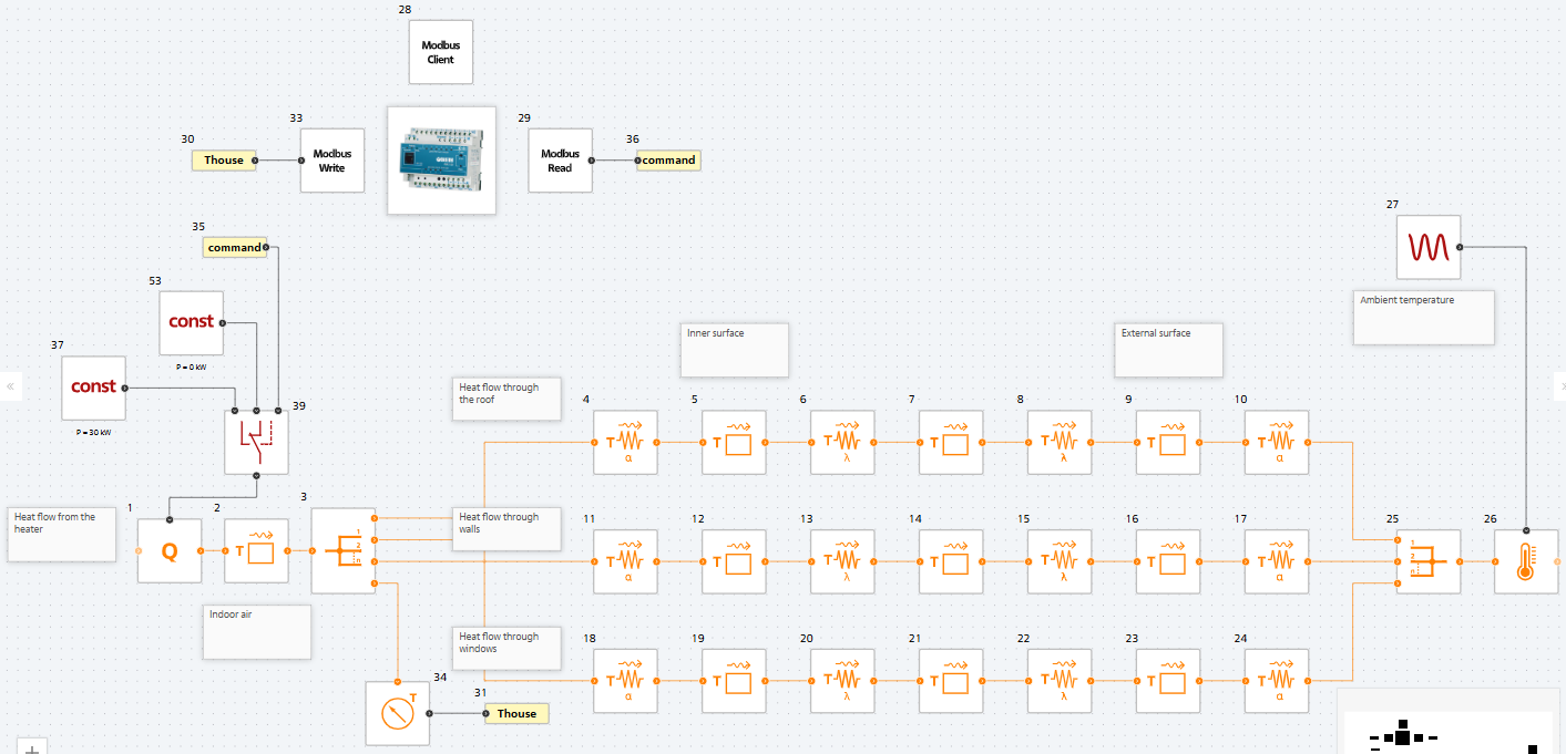
Fig. 3 Model of the home heating control system#
4. Setting up the control controller#
An Arduino UNO board was chosen as the external control controller. However, to implement the Slave device, the microcontroller must be connected to the network (router), so we connected an additional Ethernet module – the ENC28J60. The connection diagram for the Arduino UNO and ENC28J60 is shown in Fig. 4:
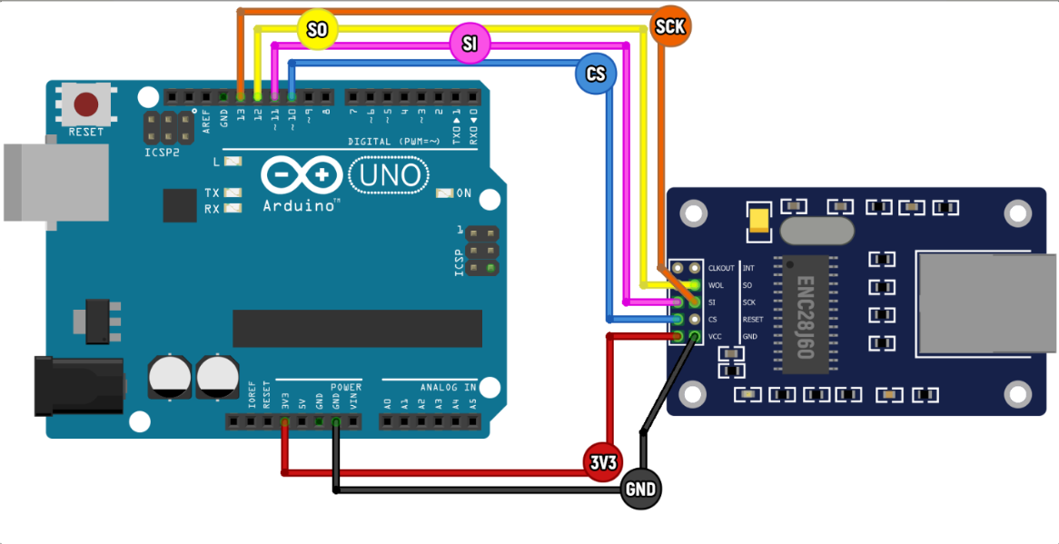
Fig. 4 Connection diagram of the ENC28J60 module to the Arduino UNO#
The next step is to write firmware for the Arduino microcontroller so that it can implement the control logic (see the section Installing Modbus blocks in REPEAT VISION). Open the Arduino IDE, create a new sketch, and describe the necessary conditions. The program code can be divided into several components:
Initialization – we specify the main libraries, temperature limits, storage register number and input register number.
#include <EtherCard.h>
#include <Modbus.h>
#include <ModbusIP_ENC28J60.h>

const int TEMPERATURE_HREG = 100; // Holding register
const int CONTROL_IREG = 101; // Input register
// Temperature limits
const int LOWER_THRESHOLD = 18;
const int UPPER_THRESHOLD = 22;
ModbusIP mb;

// State variables
int lastControlState = 0; // Tracks last control state
int lastTemperature = -100; // Initialize with impossible value
Basic settings – we enter the MAC address of the network in which the Arduino is located, and the IP address of the Arduino itself.
Important
The Arduino IP address is only determined when the board is connected to the ENC28J60 module, which in turn is connected via an Ethernet cable to the router.
void setup() {
Serial.begin(9600);
byte mac[] = { 0xDE, 0xAD, 0xBE, 0xEF, 0xFE, 0xED };
byte ip[] = { 0, 0, 0, 0 }; // IP address arduino
mb.config(mac, ip);
mb.addHreg(TEMPERATURE_HREG, 0); // Initialize with 0
mb.addIreg(CONTROL_IREG, 0); // Initialize with 0
}
Calculation part – we introduce a function that responds to Modbus requests and describe the basic logic of temperature control.
void loop() {
mb.task(); // Process Modbus requests
int currentTemp = mb.Hreg(TEMPERATURE_HREG);
// Only process if temperature changed
if (currentTemp != lastTemperature) {
if (currentTemp <= LOWER_THRESHOLD) {
lastControlState = 1; // Turn ON
}
else if (currentTemp >= UPPER_THRESHOLD) {
lastControlState = 0; // Turn OFF
}
// Update Modbus registers
mb.Ireg(CONTROL_IREG, lastControlState);
lastTemperature = currentTemp;
// Immediate debug output on change
Serial.print("Temperature: ");
Serial.print(currentTemp);
Serial.print(" | Control State: ");
Serial.println(lastControlState);
}
// Periodic status report
static unsigned long lastPrint = 0;
if (millis() - lastPrint > 5000) {
lastPrint = millis();
Serial.print("[Status] Temp: ");
Serial.print(mb.Hreg(TEMPERATURE_HREG));
Serial.print(" | Control: ");
Serial.println(mb.Ireg(CONTROL_IREG));
}
}
For easy monitoring of information, the calculation portion of the code includes lines displaying register value changes in the Port Monitor, a terminal window in the Arduino IDE. After flashing the board with this code, the terminal will display information on both registers, updated every second. Fig. 5:
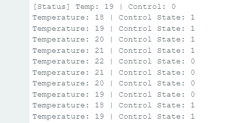
Fig. 5 Information from the Port Monitor when interacting with the model#
5. Assembly of the entire system#
The final step in building the home heating model control system is assembling both parts into a single structure. Connect the laptop with the REPEAT VISION model to the network via an Ethernet cable, then connect the Arduino with the module to the same laptop via a USB A-B cable. The ENC28J60 module, in turn, must also be connected to the network via an Ethernet cable. The physical system is shown in Fig. 6 below.
Important
Both the laptop and Arduino must be on the same network and connected to the same router so that the model can communicate with the board via Modbus TCP.
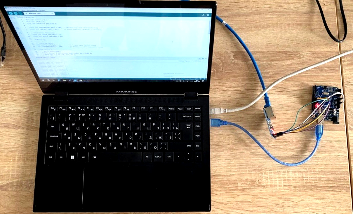
Fig. 6. Physical part of the home heating control system#
When you connect the Arduino board to the laptop, it automatically powers on because it receives power. Consequently, the firmware previously installed on it begins executing from the first seconds of power-up. Go to REPEAT VISION and fill in the Modbus block properties.
The IP address of the Arduino UNO was specified in the program code.
Port – default 502.
Connection timeout – 3000 [ms].
Word order is straight (Big Endian).
We specify the block Modbus Client Settings as the client.
Slave ID – default 1.
Write operation type – Storage registers.
Data type – uint16.
The address of the first register is 100, specified in the code (TEMPERATURE_HREG).
We specify block №28 Modbus Client Settings as the client.
Slave ID – default 1.
Read operation type – Input registers.
Data type – uint16.
The address of the first register is 101, specified in the code (CONTROL_IREG).
Once you’ve finished setting up the model, be sure to save it and verify that the physics and thermal models are configured correctly. Finally, connect the Arduino to the laptop and run the model.
6. Results#
The simulation results are in the ‘Visualization’ tab. The first graph (see Fig. 7 below) shows changes in the temperature of the thermal mass (2). The graph looks like a staircase; upon closer inspection, it’s clear that the temperature varies between 18 and 22°C, as specified by the model. Fig. 8 shows changes in the remaining thermal masses in the house heating model.
You can also control the reading of signals from the Arduino via Modbus Read (see Fig. 9 below).
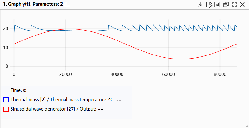
Fig. 7 Graph of change in temperature of thermal mass (2)#
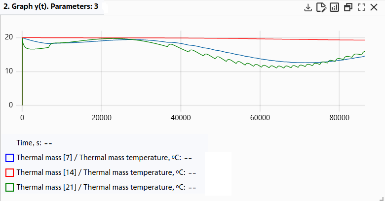
Fig. 8 Changes in the temperature indicators of thermal masses (7), (14), (21)#
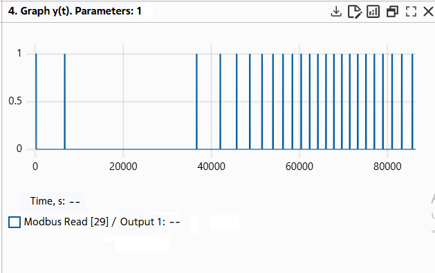
Fig. 9 Changing the Modbus Read output signal#
7. Conclusion#
Thus, a home heating control system based on the Modbus TCP protocol was implemented using an Arduino UNO microcontroller and an ENC28J60 Ethernet module. Testing confirmed the functionality of the proposed solution, including stable data transmission and correct processing of Modbus requests.